
Wide-angle lens system

a wide-angle lens and lens body technology, applied in the field of wide-angle lens systems, can solve the problems of increasing the difficulty of miniaturization and excessive image edge compression

Active Publication Date: 2008-11-04
LARGAN PRECISION
View PDF1 Cites 116 Cited by
  • Summary
  • Abstract
  • Description
  • Claims
  • Application Information

AI Technical Summary

Benefits of technology

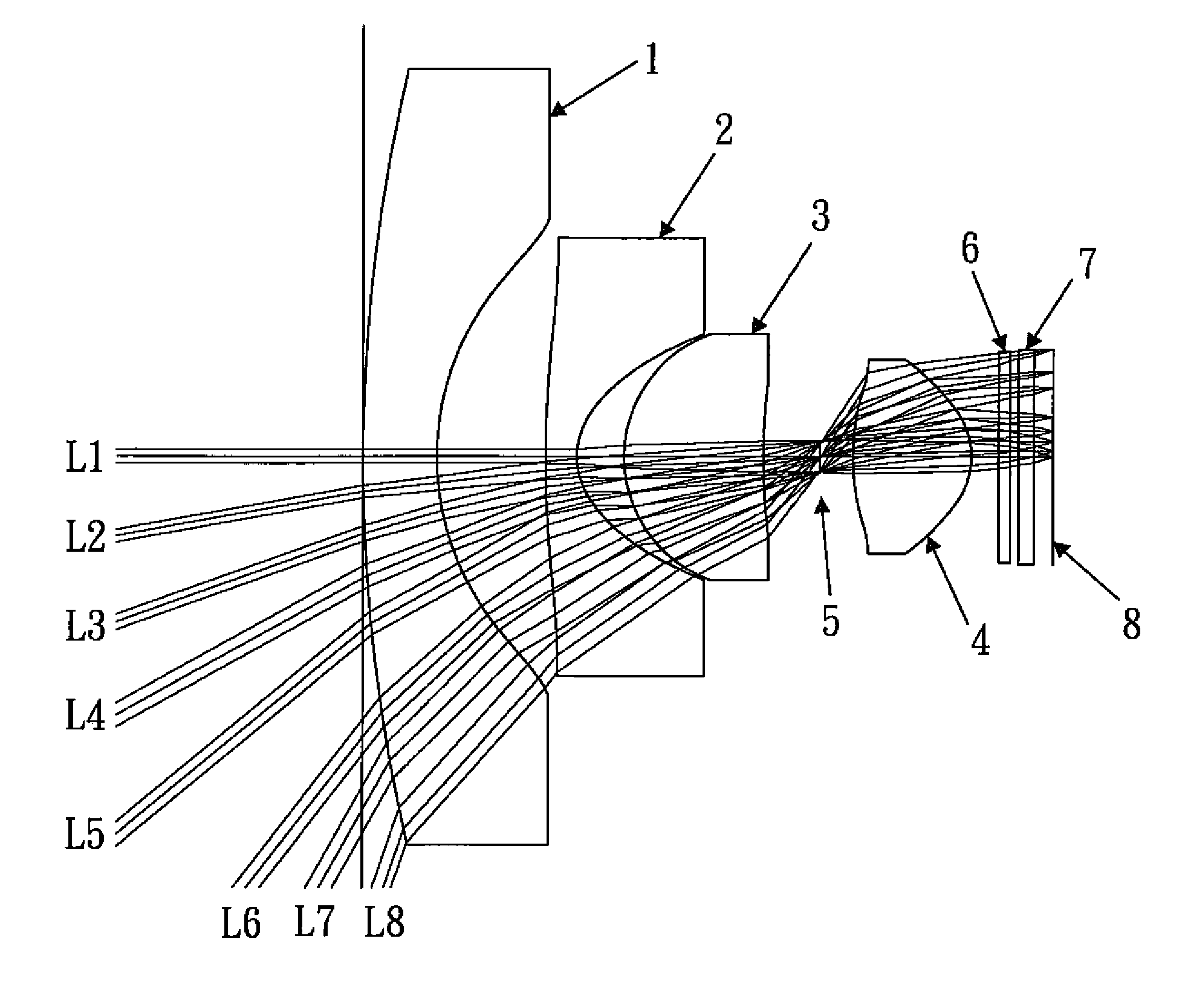
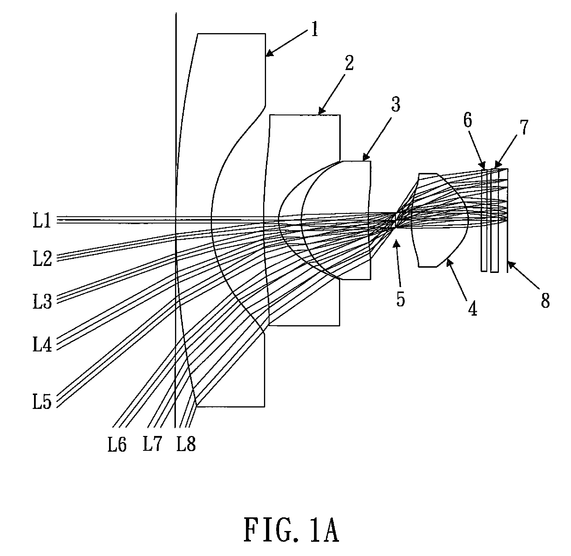
[0009]The primary objective of the present invention is to provide a wide-angle lens system which comprises four lens elements and an aperture stop arranged sequentially from the object side to the image side as follows: the first lens element, the second lens element, the third lens element, the aperture stop, and the fourth lens element. The first and second lens elements are negative meniscus lens elements with an object-side convex surface, and both of the third and fourth lens elements are biconvex. At least four of the surfaces of the first, second and third lens elements are aspheric surfaces, and both surfaces of the fourth lens element are aspheric. Such arrangements can produce an aberration compensation effect with the least number of lens elements.
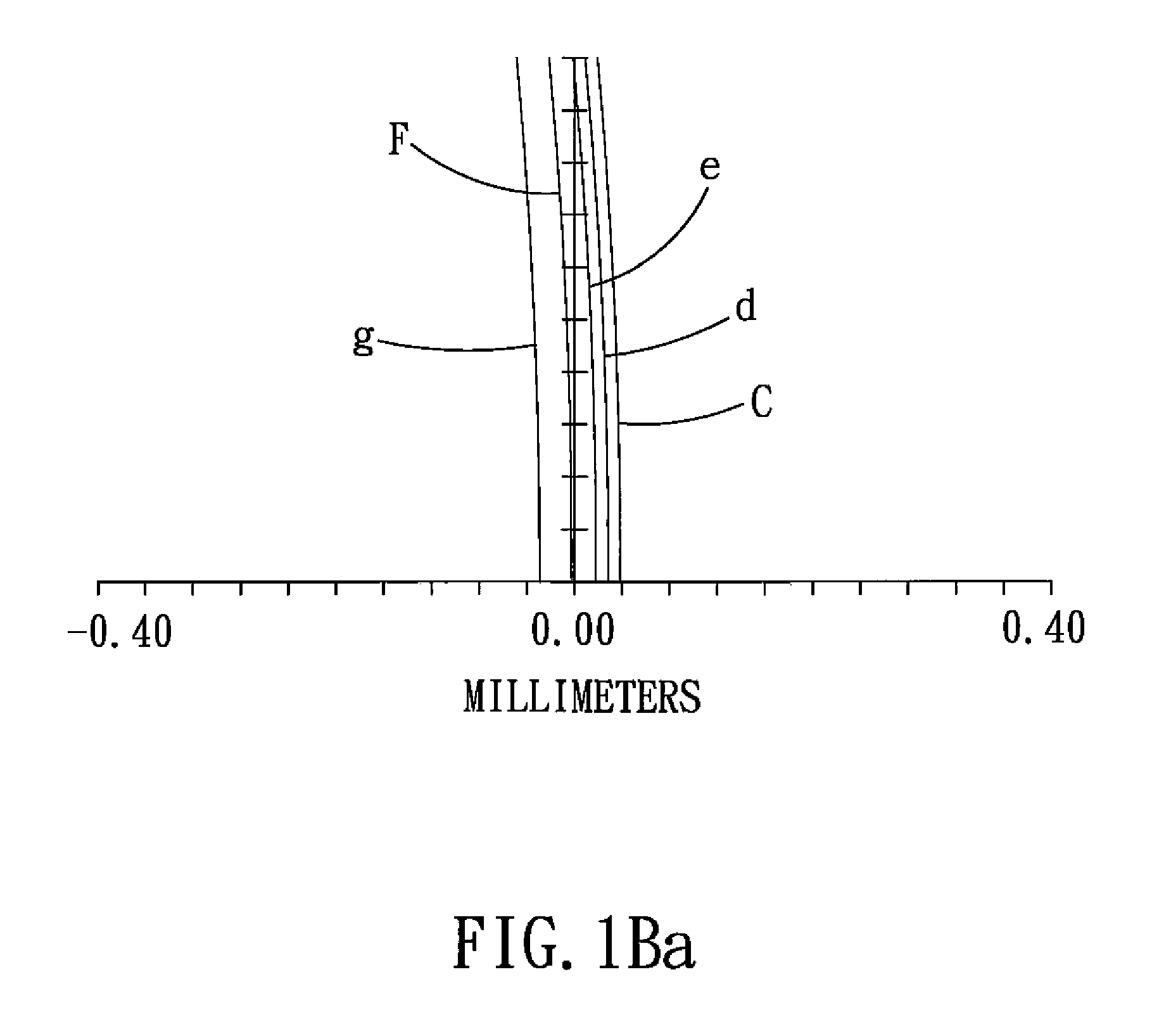
[0010]When the field of view of the wide-angle lens system is 140 degrees, under the effect of the negative refractive power of the first and second lens elements, the incident light will enter the third lens element at an adjusted angle. However, the light passed through the second lens element still has negative distortion aberration, astigmatic aberration, and magnification chromatic aberration, which can be compensated by the positive refractive power of the third and fourth lens elements. It is apparent that even if the field of view of the wide-angle lens system is as high as 140 degrees, the extreme distortion of the image edge can be prevented with the least four lens elements, and the image has a high sharpness.
[0012]When f123 / f>−8.0, the negative refractive power of the first and second lens elements will increase and cause excessive compression of the image edge, which needs to be compensated by image processing technology. When f123 / f<−15.0, to guide the incident light with field of view of 140 degrees, the outer diameter of the first lens element must increase accordingly, thus increasing the difficulty of miniaturization.

Problems solved by technology

When f123 / f>−8.0, the negative refractive power of the first and second lens elements will increase and cause excessive compression of the image edge, which needs to be compensated by image processing technology.
When f123 / f<−15.0, to guide the incident light with field of view of 140 degrees, the outer diameter of the first lens element must increase accordingly, thus increasing the difficulty of miniaturization.

Method used


Image

  • Wide-angle lens system
  • Wide-angle lens system
  • Wide-angle lens system

Examples


Embodiment Construction

[0047]The present invention will be clearer from the following description when viewed together with the accompanying drawings, which show, for purpose of illustrations only, the preferred embodiment in accordance with the present invention.

[0048]FIGS. 1-7 show the respective embodiments of a wide-angle lens system in accordance with the present invention, which are particularly used in the monitor or vehicle-related lens system with a field of view of approximately 140 degrees, and FIGS. 1A-7A show the respective embodiments of a wide-angle lens system in accordance with the present invention. The wide-angle lens system comprises, from the object side to the image side: a first lens element1, a second lens element 2, a third lens element 3, an aperture stop 5, a fourth lens element 4, an IR (infrared) filter 6, a glass cover 7, and an image plane 8.

[0049]The first lens element 1 is a negative meniscus element with a convex object-surface surface. The second lens element 2 is a nega...


PUM


Abstract

A wide-angle lens system comprises, sequentially from the object side to the image side: a first lens element, a second lens element, a third lens element, an aperture and a fourth lens element. If the field of view of the wide-angle lens system is as high as 140 degrees, the extreme distortion of the image edge can be prevented with only four lens elements, and the image has a high sharpness. Therefore, it is very suitable for use in the monitor and vehicle-related lens system.

Description

BACKGROUND OF THE INVENTION[0001]1. Field of the Invention[0002]The present invention relates to a wide-angle lens system comprising a first lens element, a second lens element, a third lens element, an aperture stop, and a fourth lens element, and more particularly to a super wide-angle lens system which is suitable for use in monitor or vehicle, and whose field of view is as high as 140 degrees.[0003]2. Description of the Prior Art[0004]The biggest problem in designing a conventional wide-angle lens system is that the problem of image distortion will occur after the object image is processed by the lens system. However, in the past, only the spherical glass lens can be manufactured and in order to compensate the negative distortion aberration (also called barrel distortion, namely, image magnification decreases with increasing distance from the optical axis, and the straight lines are curved in image), a plurality of negative and positive meniscus lens elements should be arranged ...

Claims


Application Information

Patent Timeline
Patent Type & Authority Patents(United States)
IPC IPC(8): G02B9/34G02B3/02
CPCG02B13/06
Inventor NODA, SAYURI
Owner LARGAN PRECISION
Learn More