
Head-up projection system

a projection system and head-up display technology, applied in the field of projection systems, can solve the problems of difficult self-installation by the driver or operator of the cost of installing the head-up display system in the vehicle is relatively high, and the conventional head-up display system installed in the vehicle can only be used to display driving information images when the vehicle is in use, etc., to achieve the effect of convenient and simple installation, less cost to produce and install, and convenient us

Active Publication Date: 2014-10-23
DELTA ELECTRONICS INC
View PDF5 Cites 12 Cited by
  • Summary
  • Abstract
  • Description
  • Claims
  • Application Information

AI Technical Summary

Benefits of technology

The present invention provides a head-up projection system that is easy to install and can be used in a variety of vehicles without being too costly. The system has a different optical path than conventional systems, resulting in better image resolution and better control over image size. This system also avoids image distortion. Additionally, the roof-mounted version of the system has a simple structure, making it easy for drivers to install on their own.

Problems solved by technology

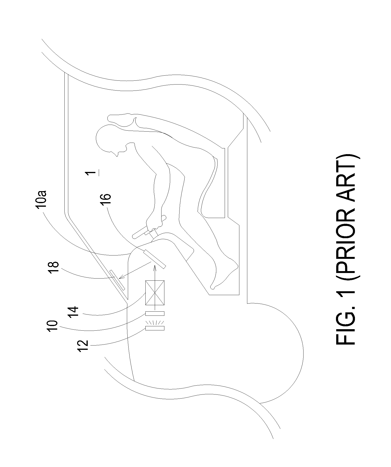
It is hard for the driver or operator to self install the head-up display system in the vehicle, and the cost of installing the head-up display system in the vehicle is relatively high.
In addition, the conventional head-up display system installed in the vehicle can only be used to display driving information image when the vehicle is in use.
However, when the vehicle isn't in use, the head-up display system are turned off and can't be taken away from the vehicle to provide various presentation or image display functions outside the vehicle.
Furthermore, the conventional head-up display system projecting the light directly upon the specific area of the windshield usually requires a coating material that significantly decreases the transparency of the windshield.
As a result, the conventional head-up display system is restricted to limited region upon the windshield.
In addition, the image resolution of the conventional head-up display system doesn't conform to the practical requirements, and the image size projected on the specific area of the windshield can't be well controlled and may be smaller than the specific area of the windshield.
Furthermore, the driving information image projected from the conventional head-up display system can only be displayed at the specific area of the windshield, and the conventional head-up display system can't adjust or change the image display height of the driving information image according to the eyes positions of various drivers.

Method used


Image

  • Head-up projection system
  • Head-up projection system
  • Head-up projection system

Examples


Embodiment Construction

[0033]The present invention will now be described more specifically with reference to the following embodiments. It is to be noted that the following descriptions of preferred embodiments of this invention are presented herein for purpose of illustration and description only. It is not intended to be exhaustive or to be limited to the precise form disclosed.

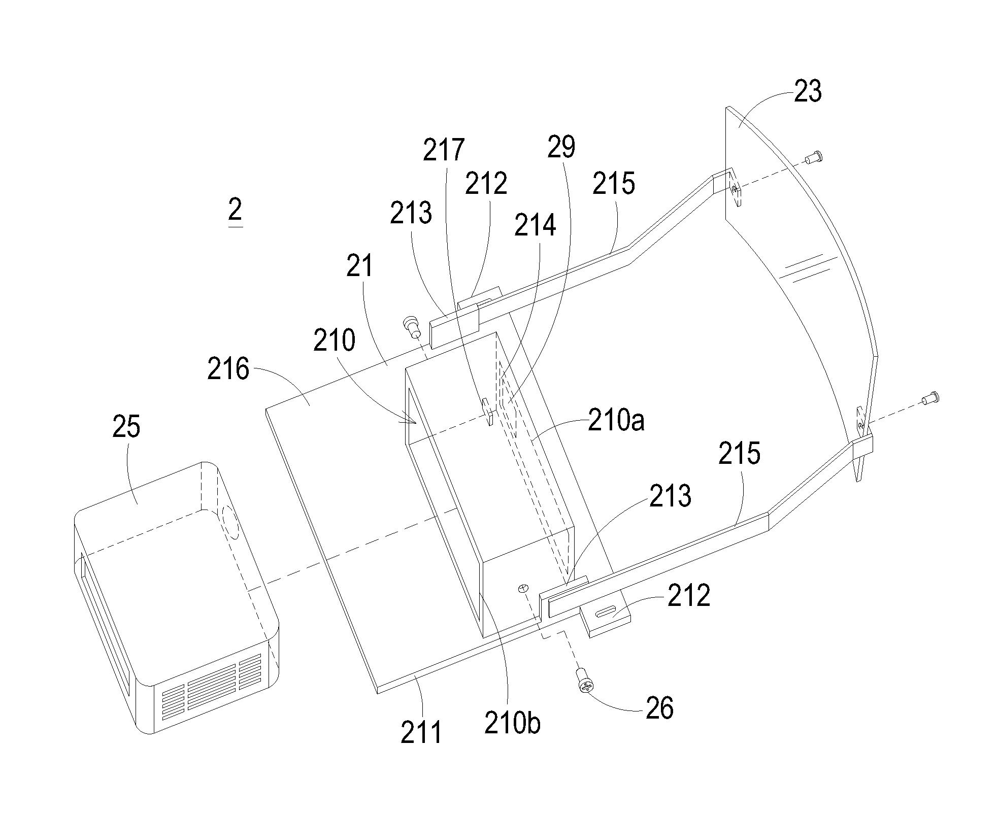
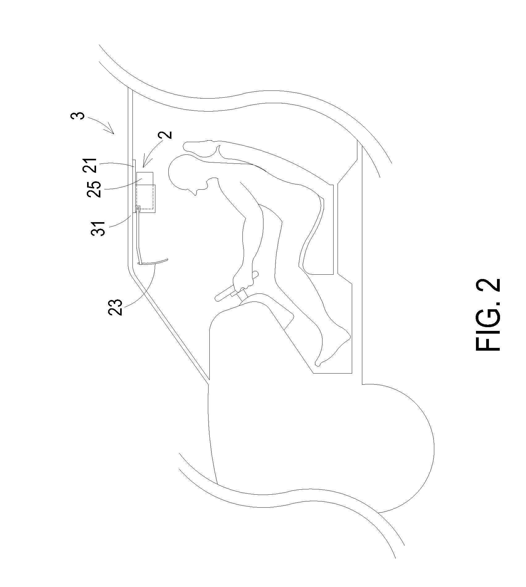
[0034]Please refer to FIGS. 2, 3A and 3B. FIG. 2 schematically illustrates a head-up projection system for displaying navigation information in a vehicle according to a first preferred embodiment of the present invention. FIG. 3A schematically illustrates the configuration of the head-up projection system as shown in FIG. 2, wherein the portable projector is detached from the mounting member. FIG. 3B schematically illustrates the configuration of the head-up projection system as shown in FIG. 2, wherein the portable projector is accommodated in the receptacle of the mounting member. The head-up projection system 2 of the present ...


PUM


Abstract

A head-up projection system is disclosed. The head-up projection system comprises a mounting member and a portable projector. The mounting member has a receptacle, and the mounting member is mounted on a roof of a vehicle. The portable projector is detachably installed in the receptacle of the mounting member and configured to connect with a mobile communication and computing device with a navigation function for displaying a navigation information image in the vehicle from the mobile communication and computing device.

Description

CROSS-REFERENCE TO RELATED APPLICATION[0001]This application claims the benefit of U.S. Provisional Application No. 61 / 813,834 filed on Apr. 19, 2013, and entitled “HEAD-UP PROJECTION SYSTEM”, the entirety of which is hereby incorporated by reference.FIELD OF THE INVENTION[0002]The present invention relates to a projection system, and more particularly to a head-up projection system for displaying navigation information.BACKGROUND OF THE INVENTION[0003]In recent years, navigation system is widely used to guide a traveler to a desired destination. Usually, a global positioning system (GPS) transceiver and a navigation database are employed in the navigation system for obtaining the location of the traveler. Then, the position of the traveler is compared to a desired destination by a central processing unit of the navigation system, and visual and audio indications for guiding the traveling routes to the desired destination can be provided to the traveler via the display and loudspeak...

Claims


Application Information

Patent Timeline
Patent Type & Authority Applications(United States)
IPC IPC(8): G02B27/01
CPCG02B27/0101G02B5/02G02B27/0149G02B2027/0156
Inventor JAN, SHENG-HSIUNGLAI, TU-FA
Owner DELTA ELECTRONICS INC
Learn More