
Charging cabinet

a charging cabinet and charging port technology, applied in the direction of revolving cabinets, coupling device connections, instruments, etc., can solve the problems of unsightly and dangerous clutter, unnecessary clutter, and inefficient distribution of devices in several rooms for the purpose of charging, so as to eliminate the safety concerns of loose power cords and eliminate clutter.

Inactive Publication Date: 2008-11-04
LABYRINTH WORLDWIDE
View PDF19 Cites 42 Cited by
  • Summary
  • Abstract
  • Description
  • Claims
  • Application Information

AI Technical Summary

Benefits of technology

"The present invention provides a charging cabinet for small electronic devices. The charging cabinet has a shelf for placing electronic devices, a housing for containing the shelf, and multiple power outlets built into the shelf for delivering power to the devices. The charging cabinet eliminates the need for dedicated space on a desktop or counter and reduces clutter. It also eliminates safety concerns by containing power cords. The charging cabinet can be used in kitchens, bathrooms, or other areas where multiple electronic devices need to be charged and stored."

Problems solved by technology

Thus, charging multiple electronic devices through different outlets necessitates that consumers dedicate multiple power outlets to the devices.
If a household or office does not have enough outlets in any one room, then a consumer may have to distribute the devices throughout several rooms.
Distributing the devices throughout several rooms for the purpose of charging them is inefficient at least from the perspective of having to go to different rooms when it is time to use or collect one or more of the devices.
Additionally, the cords that connect a device to a power outlet are often long and may impede traffic, creating safety concerns.
Finally, having multiple cords in an area results in unsightly and dangerous clutter.
However, this alternative still results in unnecessary clutter and the cords may still create safety concerns.
Furthermore, storing and charging multiple electronic devices on a kitchen or bathroom counter, desk, or elsewhere significantly reduces the counter's or desk's usable space, further creating unsightly clutter.

Method used


Image

  • Charging cabinet
  • Charging cabinet
  • Charging cabinet

Examples


Embodiment Construction

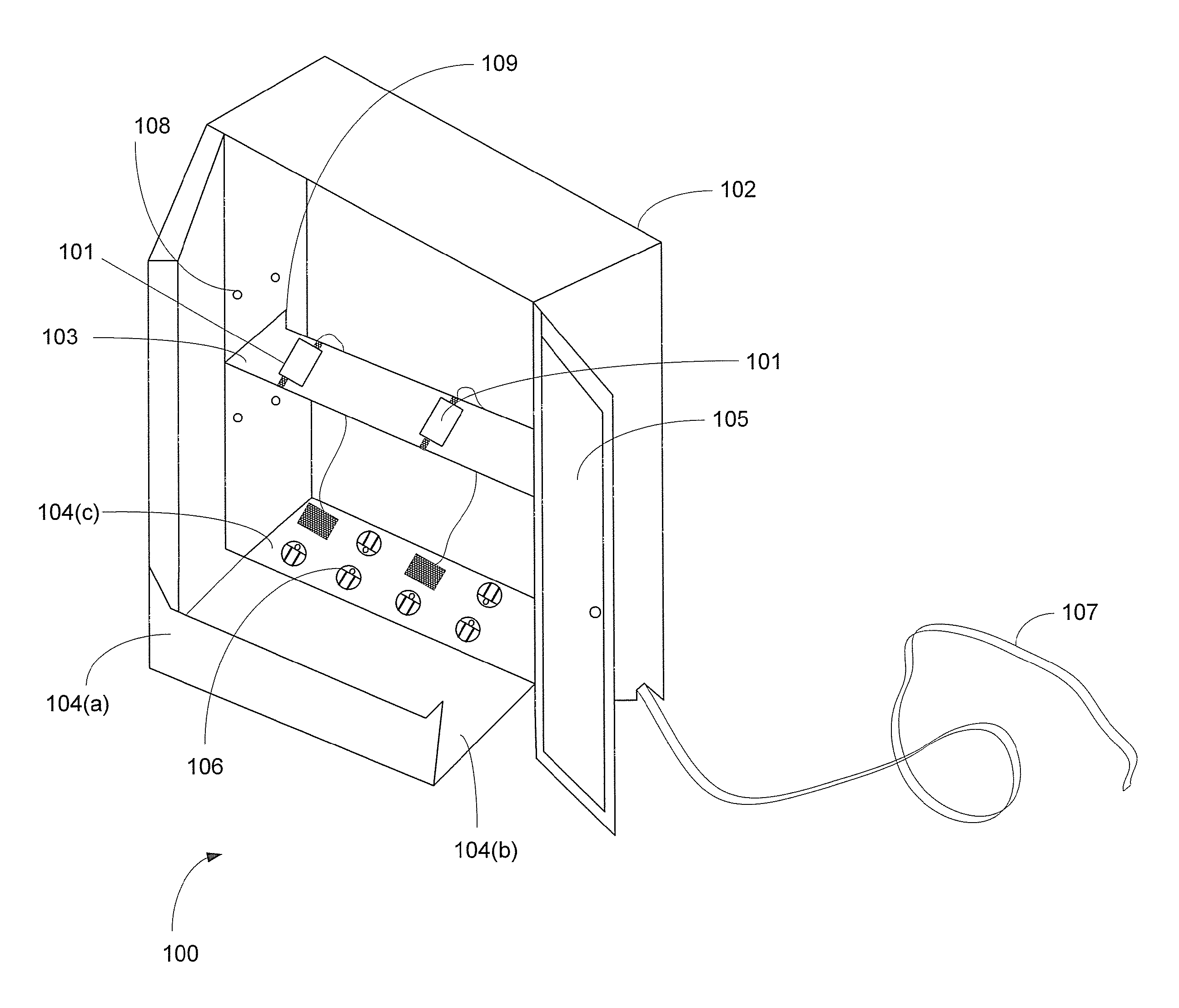
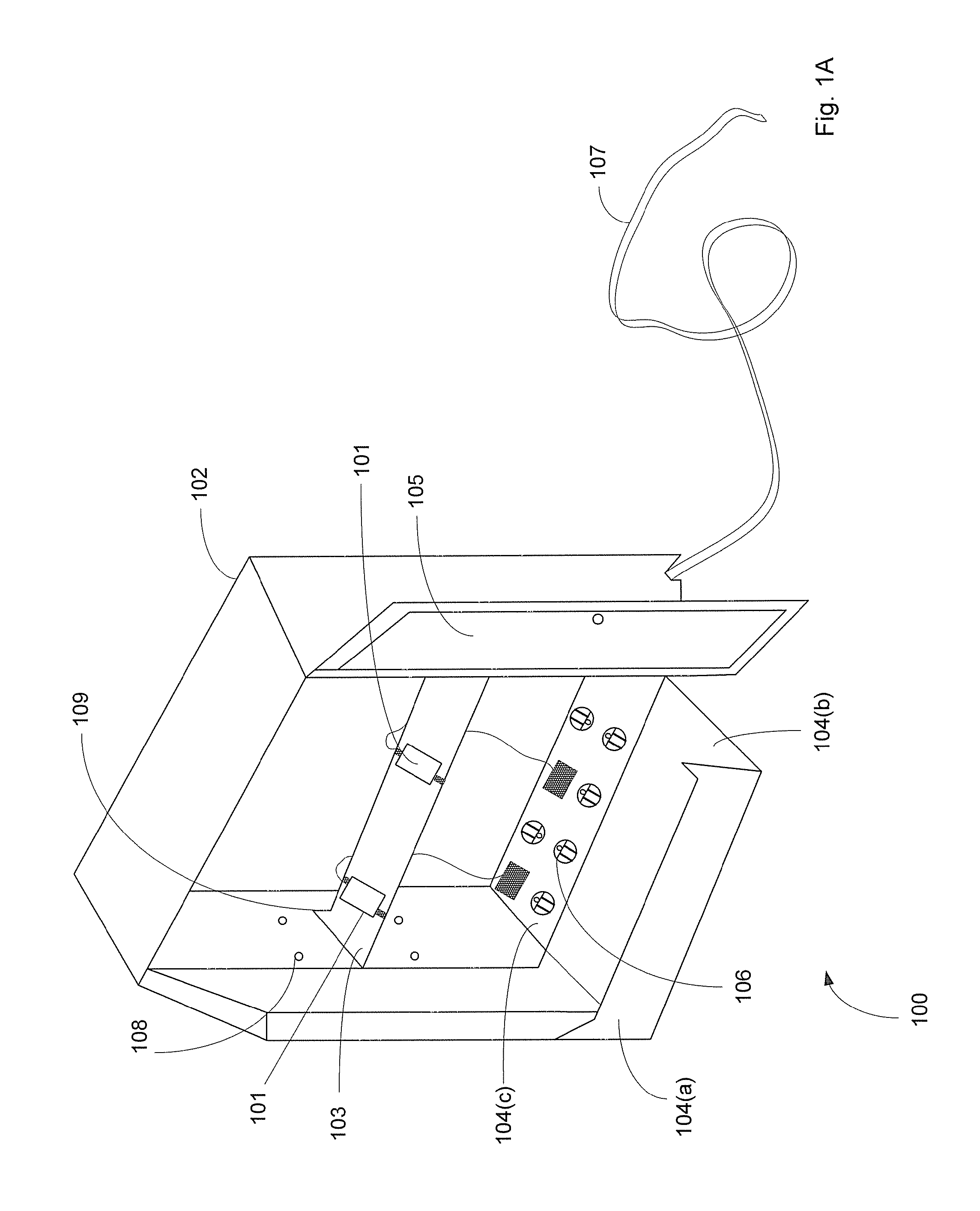
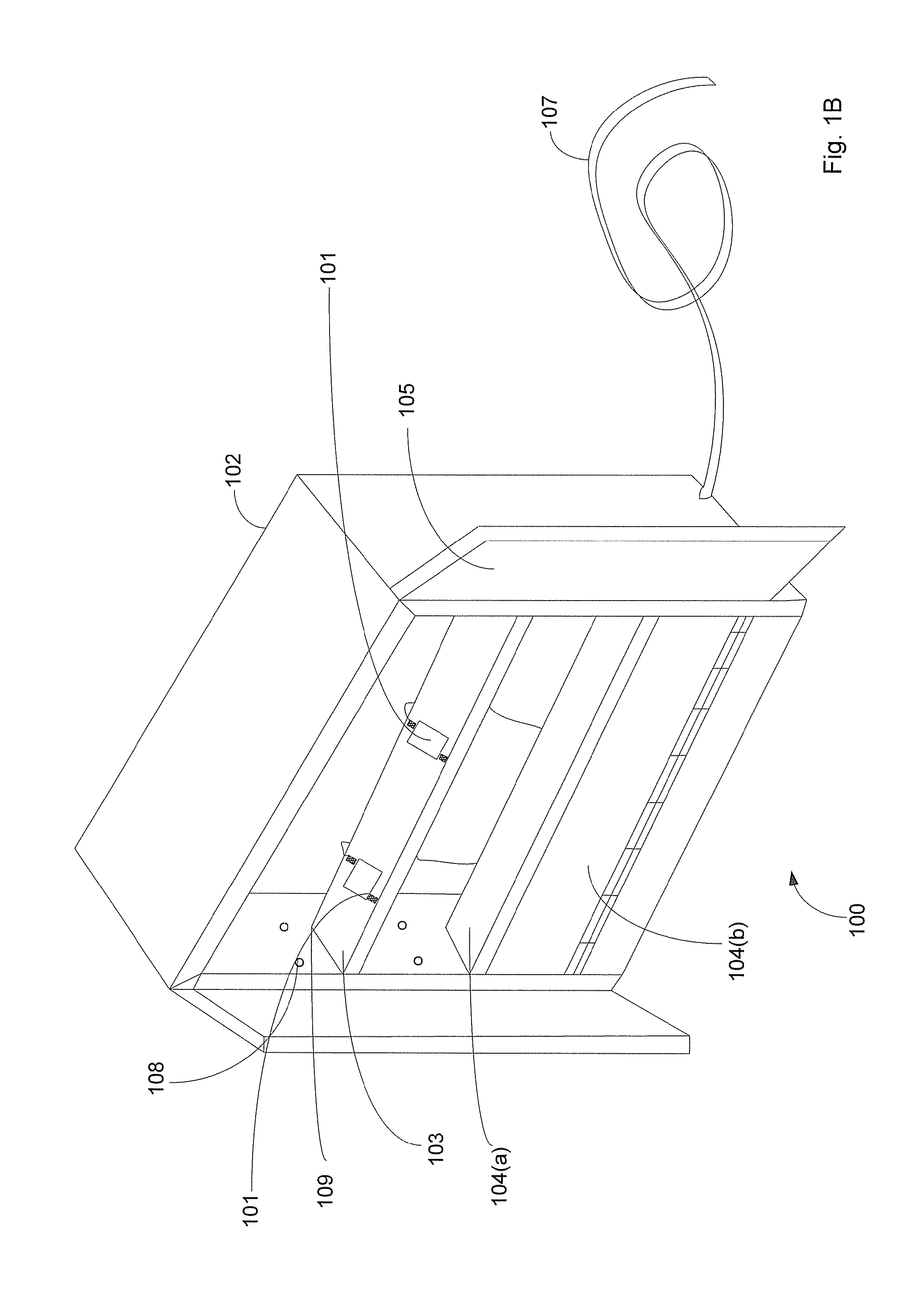
[0015]Referring to the drawings, FIG. 1A illustrates a charging cabinet in accordance with an exemplary embodiment. It should be understood, however, that this and other arrangements shown and described herein are exemplary only, and that many variations are possible. For instance, various elements could be combined, distributed, added, or omitted.

[0016]As generally illustrated in FIG. 1A, charging cabinet 100 includes electronic devices 101, housing 102 , shelf 103 , shelf 104, doors 105, power outlets 106, power cord 107, and ventilation outlets 108. Electronic devices 101 may be cellular telephones, personal digital assistants (“PDA”), iPod® music players, electronic toothbrushes, electronic razors, digital cameras, GameBoy® hand-held video games, or other similar devices. The charging cabinet 100 may house or charge a multitude of such devices at a time. The charging cabinet may house or charge a plurality of homogenous devices. Alternatively, the devices may be heterogeneous. H...


PUM


Abstract

An exemplary embodiment of the present invention has been described above. Those skilled in the art will understand, however, that changes and modifications may be made to this embodiment without departing from the true scope and spirit of the present invention, which is defined by the claims.

Description

BACKGROUND[0001]1. Field of the Invention[0002]This invention relates to storage cabinets.[0003]2. Description of Related Art[0004]Small electronic devices have grown to replace many of the older, bulkier devices consumers were accustomed to using. The smaller electronic devices are popular not only because of their smaller size and lighter weight, but also because they are portable, allowing consumers to take and use them anywhere—be it at home, at work, on vacation, in the car, etc. Due to the ever-popular portability of such small electronic devices, it is often the case that consumers use or carry several such devices at the same time. For example, a consumer may carry a cellular telephone, a personal digital assistant (“PDA”), and an iPod® music player, all at the same time. Similarly, consumers may have some or all such devices at their desks at work. Further, at home, a user may have all previously mentioned devices plus an electric toothbrush and an electric shaving razor, t...

Claims


Application Information

Patent Timeline
Patent Type & Authority Patents(United States)
IPC IPC(8): A47B97/00
CPCA47B97/00H02J7/0027G07F15/006H02J7/0013H02J7/0044H02J2310/22
Inventor COLLINS, STEPHENCOLLINS, SUZZANE
Owner LABYRINTH WORLDWIDE
Learn More