
Mine resistant band track

a band track and resistance technology, applied in the direction of inflatable tyres, mechanical equipment, transportation and packaging, etc., can solve the problems of limited use of land mines, mobility failure, and maintenance of the mobility of armored vehicles, and achieve the effect of preventing the development of large shearing forces

Inactive Publication Date: 2008-11-04
UNITED STATES OF AMERICA THE AS REPRESENTED BY THE SEC OF THE ARMY
View PDF20 Cites 11 Cited by
  • Summary
  • Abstract
  • Description
  • Claims
  • Application Information

AI Technical Summary

Benefits of technology

"The invention provides a new and improved band track assembly that can withstand explosive charges. The assembly includes a track pad with extended end walls that give the track pad a certain height and distance the vulnerable portion of the track band from the shearing force of an exploding mine. The end walls are curved to deflect rather than transmit the large compressional forces of the blast. The track pad end walls collapse in a controlled manner to form a continuous physical barrier protecting the vulnerable section of the band track from shrapnel and any other entrained ejecta of the explosion. The invention also includes a wheel and track assembly employing the afore-described track pad and track assembly."

Problems solved by technology

Historically, warfare scenarios and deployment techniques have limited the use of land mines to certain well defined situations to impede or channel opposing forces.
Introduction of mechanically emplaced and air-delivered mines on the modern battlefield has compounded the problem of maintaining the mobility of armored vehicles.
Charges of this type cause a mobility failure by breaking track sections and temporarily stalling armored vehicles, such as tanks, which can then be destroyed by artillery and anti-tank weapons generally placed to cover a mined area.
Blast mines generally have two damaging mechanisms operative when exploded.
Band type tracks employ flexible material and are generally more vulnerable to being rendered inoperable by mines than are conventional chain-like hinge pinned type tracks.
In most cases, it is likely that the band track failure is caused by both damaging mechanisms.

Method used


Image

  • Mine resistant band track
  • Mine resistant band track
  • Mine resistant band track

Examples


Embodiment Construction

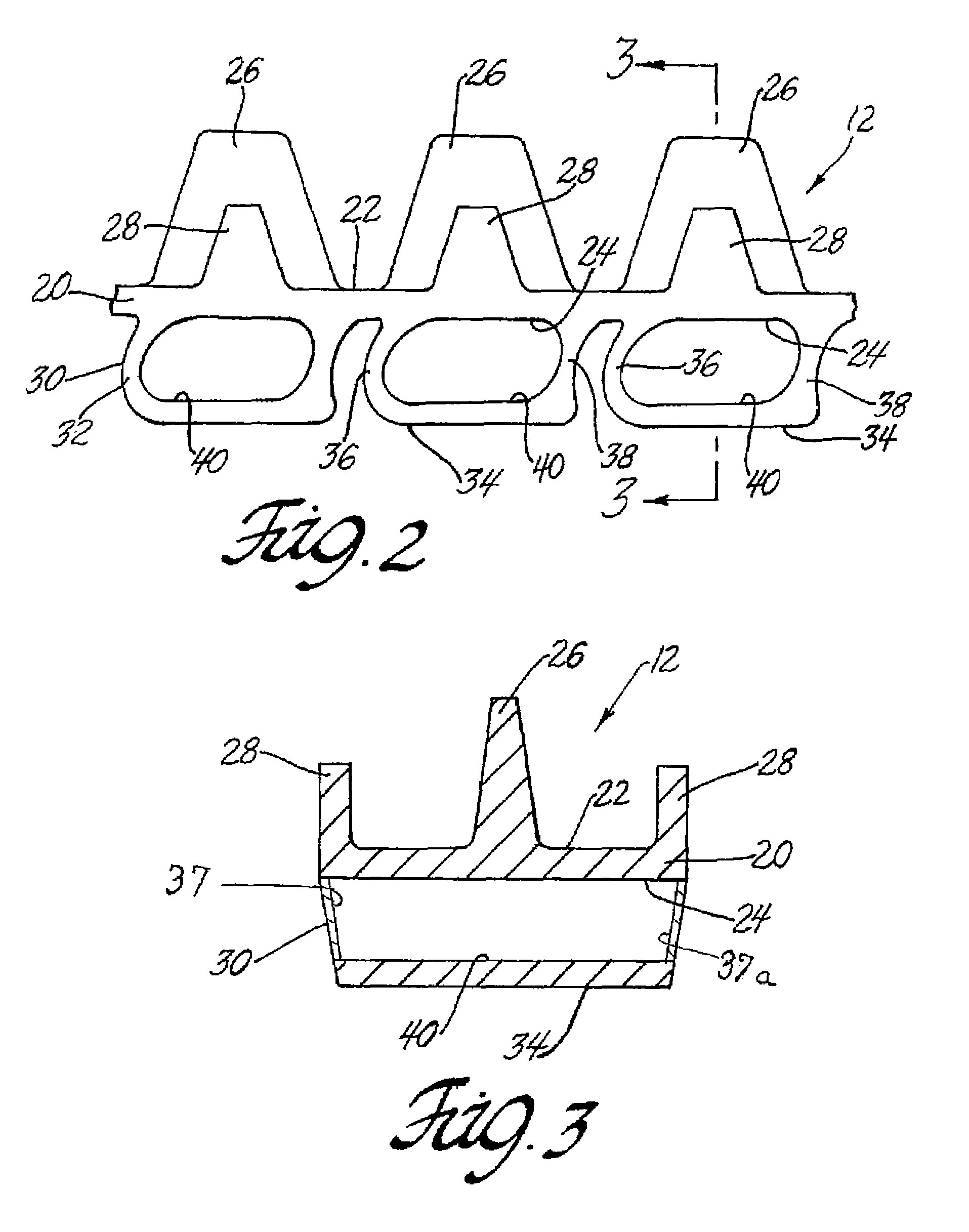
[0020]As seen in FIG. 1, a tracked vehicle 10 may be of the type that includes a band track 12 which is driven by a drive wheel 14. Band track 12 is further entrained about multiple road wheels 16 and typically about an idler wheel 18. In a preferred embodiment shown in FIG. 2 but seen better in the cross-sectional view of FIG. 3, the subject invention band track 12 comprises a band body 20 having an inner surface 22 and an outer surface 24. A center guide 26 is disposed on inner surface 22 and typically is medially placed thereon. Further, side guides 28 are located at at least one edge, and more typically at both edges, of the inner surface 22.

[0021]Those of ordinary skill in the art will appreciate that, as in conventional wheel and track assemblies for tracked vehicles, the powered motion of the drive wheel 14 in turn causes the orbital motion of the endless band track 12 around entrained road wheels 16 and idler wheel 18. It is also to be appreciated that the same wheel and tra...


PUM


Abstract

A band track for a tracked vehicle having enhanced resistance to mines includes a plurality of track pad units disposed on the bearing surface of the track band. The track pad units have extended end walls of sufficient height to distance the vulnerable portion of the band track from the shearing force of an exploding mine. These end walls are sufficiently strong to support the vehicle as it traverses terrain, but are configured to collapse in controlled manner under the force of an exploding mine. Such explosion forces a specifically configured front end wall of a trailing track pad to engage the matingly configured end wall of the leading track pad. The resulting mating juxtaposition of the adjacent end walls forms a relatively continuous physical barrier protecting the vulnerable section of the band track from shrapnel and other entrained ejecta of the explosion.

Description

STATEMENT OF GOVERNMENT INTEREST[0001]The invention described herein may be manufactured and used by or for the United States Government for governmental purposes without the payment of any royalties therefore or thereon. This patent is expected to be assigned to the United States Government.BACKGROUND OF THE INVENTION[0002]1. Field of the Invention[0003]The instant invention relates to band tracks for tracked vehicles, and more particularly, the instant invention relates to a mine resistant band track for tracked military vehicles, such as tanks, armored personnel carriers and the like.[0004]2. Technical Considerations and Prior Art[0005]Historically, warfare scenarios and deployment techniques have limited the use of land mines to certain well defined situations to impede or channel opposing forces. Advance knowledge of mine field locations could permit effective countermeasures using mine-clearing equipment, such as mine-clearing rollers mounted on lead vehicles, projected explos...

Claims


Application Information

Patent Timeline
Patent Type & Authority Patents(United States)
IPC IPC(8): B62D55/24B62D55/247
CPCB62D55/26F41H7/04
Inventor GONZALEZ, RENE G.
Owner UNITED STATES OF AMERICA THE AS REPRESENTED BY THE SEC OF THE ARMY
Learn More