
Mobile body communication apparatus

a communication apparatus and mobile technology, applied in the field of mobile communication systems, can solve the problems of difficult to prevent lowering the electric field level of carriers, increasing the bit error rate (ber), etc., and achieve the effect of preventing the deterioration of communication quality

Inactive Publication Date: 2008-10-28
SUMITOMO ELECTRIC IND LTD
View PDF9 Cites 0 Cited by
  • Summary
  • Abstract
  • Description
  • Claims
  • Application Information

AI Technical Summary

Benefits of technology

[0006]The inventors propose a mobile communication apparatus that enables communication with a certain level of quality at any point in a cell, particularly where communications from two base stations interfere with each other. This is done by performing positive phase adjustment of each sub-carrier, which is modulated using a multi-carrier modulation method, at the base station so that the deterioration of communication quality can be prevented.
[0007]Thus, the present invention particularly relates to a mobile communication apparatus that is capable for achieving a high quality communication level at a place where interference of communications in two cells tends to occur.
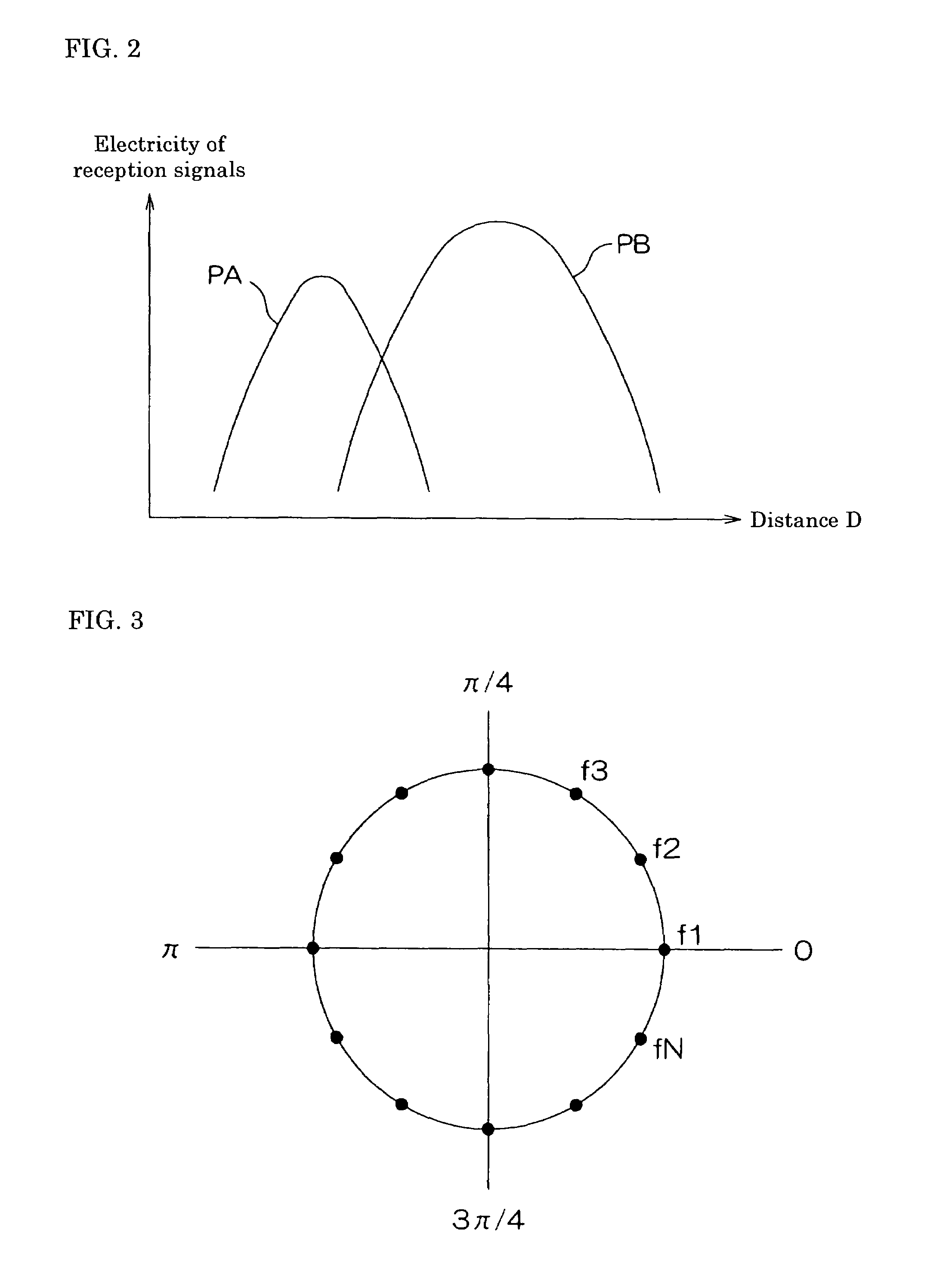
[0010]The third feature of the mobile communication apparatus of the present invention is that the mobile communication apparatus at a base station is capable of setting phase differences to the sub-carriers in a manner such that a phase shift according to the difference of a propagation distance of each sub-carrier at a reception point is taken into consideration.

Problems solved by technology

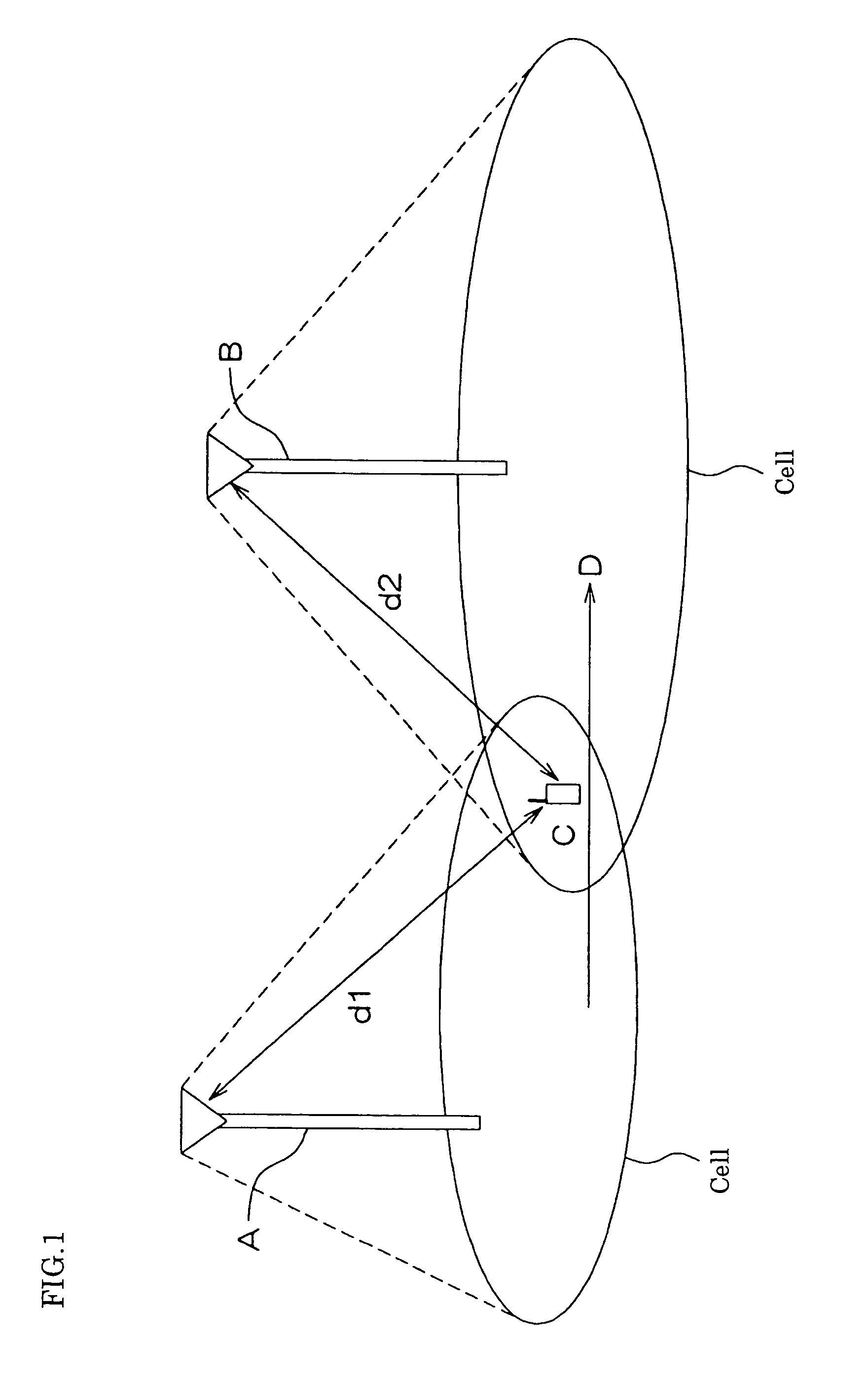
However, if the mobile station communicates with the base station at an overlapped site, that is, a place where the intensity of electric power of reception signals of a radio wave transmitted from each of the base stations is approximately equal, an interference of standing waves is generated and an electrical field level of carriers is lowered, and resultantly a Bit Error Rate (BER) is increased.
Even by these methods, it is difficult to prevent the deterioration of the communication quality, because all sub-carriers are affected by the interference of standing waves.

Method used


Image

  • Mobile body communication apparatus
  • Mobile body communication apparatus
  • Mobile body communication apparatus

Examples


Embodiment Construction

[0028]Base stations are expressed by A and B, and plural sub-carriers are expressed by f1, f2, . . . A sub-carrier is expressed representatively by fi (i=1, 2, 3, . . . ).

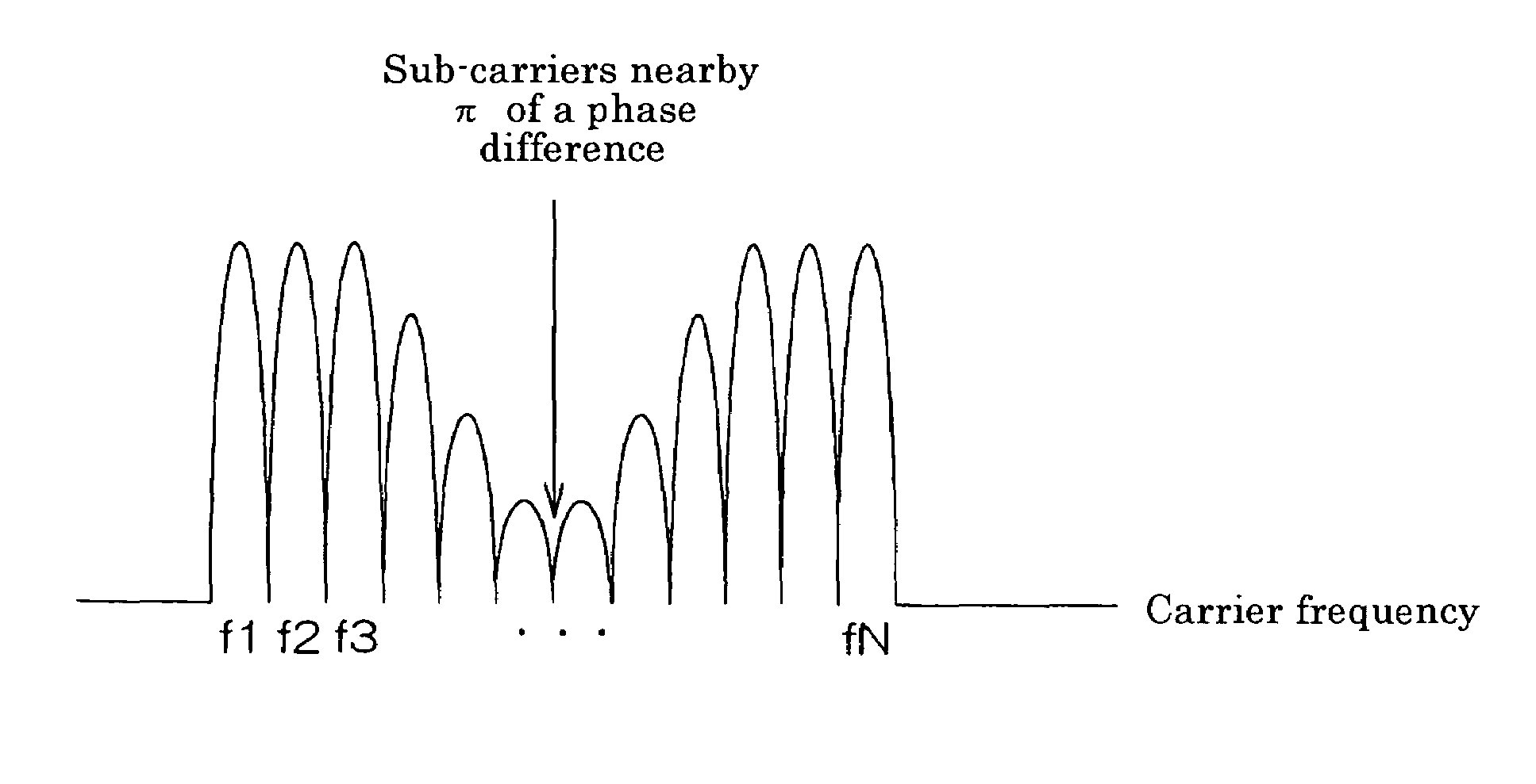
[0029]Assuming that a sub-carrier fi transmitted from a base station A and a sub-carrier fi transmitted from a base station B are synchronized (both frequencies are completely the same, and the phase differences do not change with elapse of time), the composite sub-carrier fi is attenuated at a point where a phase difference Δi between the sub-carrier fi transmitted from the base station A and the sub-carrier fi transmitted from the base station B becomes π in the area where electric power of reception signals becomes approximately equal in a communication area, in the case where these sub-carriers are not provided with phase differences, that is, the phase differences between the sub-carriers fi transmitted from the base stations A and B are the same for each sub-carrier i.

[0030]However, as in the present inventio...


PUM


Abstract

When communications of the same data are performed using a multi-carrier modulation method between a plurality of base stations and a mobile station at the same time and with the same frequency, a standing wave interference is generated to lower the carrier electric field level and the bit error rate is increased if the mobile station is located in an area where the reception powers of the electric waves from the base stations are almost identical. In order to prevent this, phase differences are set between the sub-carriers at the base station so as to enable the mobile station to avoid a situation in which all the sub-carriers are mutually cancelled. Thus, it is possible to easily correct an error, thereby improving the quality of communication.

Description

TECHNICAL FIELD[0001]The present invention relates to a mobile communication system between a mobile station and plural base stations communicating the same data at the same frequency at the same time using a multi-carrier modulation method.BACKGROUND ART[0002]In a mobile communication system, communication between a mobile station and plural base stations is carried out in communication areas (cells) formed by each base station. In a predetermined area, plural base stations are formed such that plural cells are partly overlapped. The same data are transmitted from each of the plural base stations at the same frequency at the same time.[0003]By adopting such a system configuration in the mobile communication system, a wide communication area can be formed by connecting cells in a chain-like manner, and a burden to the mobile station can be minimized.[0004]However, if the mobile station communicates with the base station at an overlapped site, that is, a place where the intensity of ...

Claims


Application Information

Patent Timeline
Patent Type & Authority Patents(United States)
IPC IPC(8): H04L27/18H04J11/00H04B7/26H04L1/00H04L27/26H04W16/18H04W88/08
CPCH04L27/2602H04L27/2626H04L27/2647H04L1/0057H04L27/2621H04B7/022H04J11/0053H04L27/2634
Inventor YOSHIDA, YUTAKAMAEHATA, TAKASHI
Owner SUMITOMO ELECTRIC IND LTD
Learn More