
Injection mold having shearing flow making part

a technology of injection mold and making part, which is applied in the direction of manufacturing tools, applications, drawing profiling tools, etc., can solve the problems of defective products, product defects, and marked decrease in reflected ligh

Inactive Publication Date: 2008-10-28
LG CHEM LTD
View PDF3 Cites 4 Cited by
  • Summary
  • Abstract
  • Description
  • Claims
  • Application Information

AI Technical Summary

Benefits of technology

[0023]It is an object of the present invention, to solve the above problems, to provide an injection mold device having a shear flow making part which is capable of manufacturing a high quality product by providing a shear flow making part, at a weldline generation area in an inside of an injection mold, for applying a searing force due to a viscosity to molten resin to adjust location of pigment mixed in the molten rein and thereby solving a problem due to poor orientation and lack of content of the pigments at a vicinity of the weldline.

Problems solved by technology

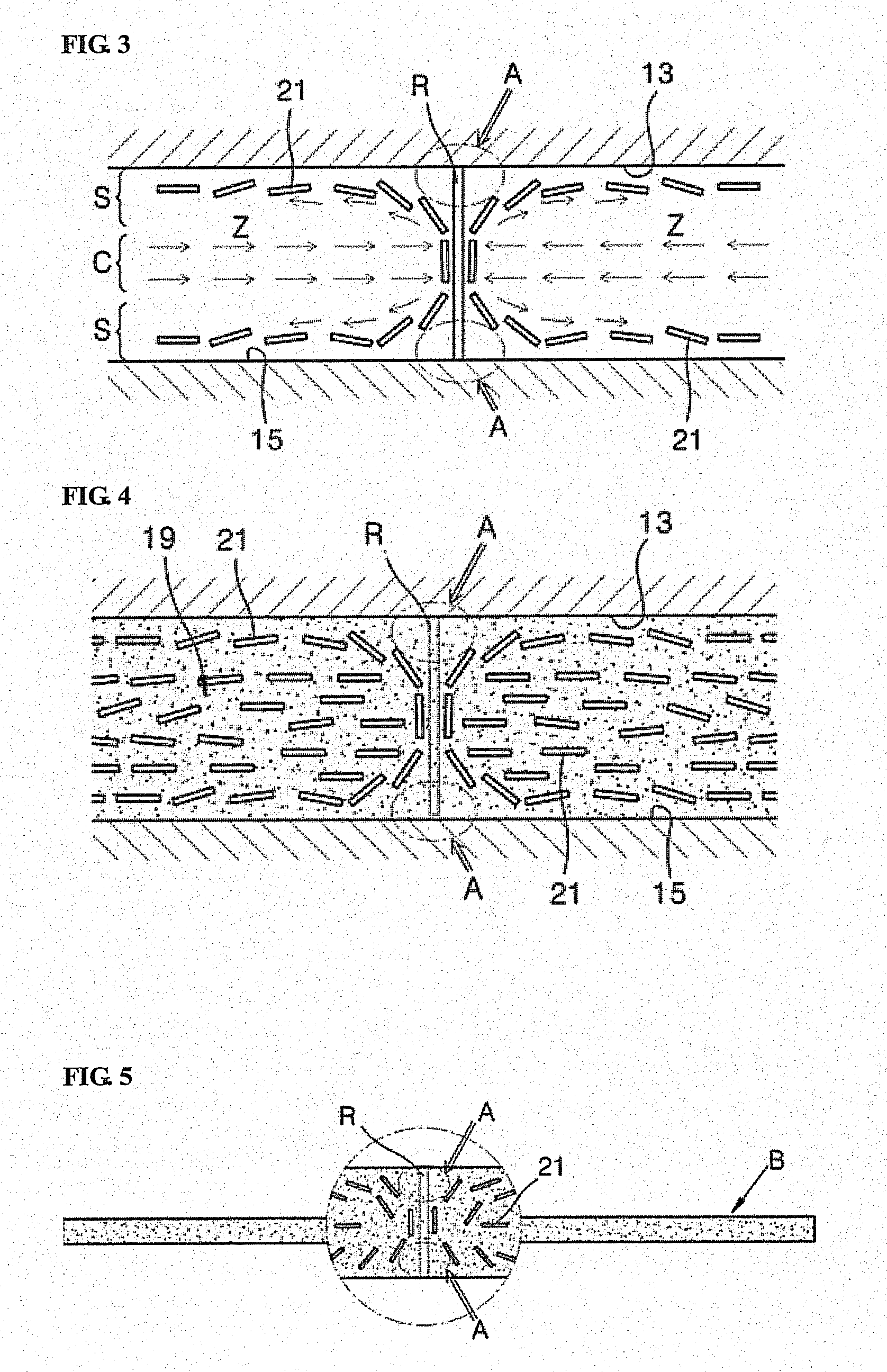
Particularly in a case that the pigment is not a polyhedron type but a flake type, an orientation of the pigment (reference symbol 21 in FIGS. 3 and 6) is perpendicular to or slant to a surface of a product and thus an amount of reflected light is markedly decreased and the portion is looked like a dark line, which results in a defective product.
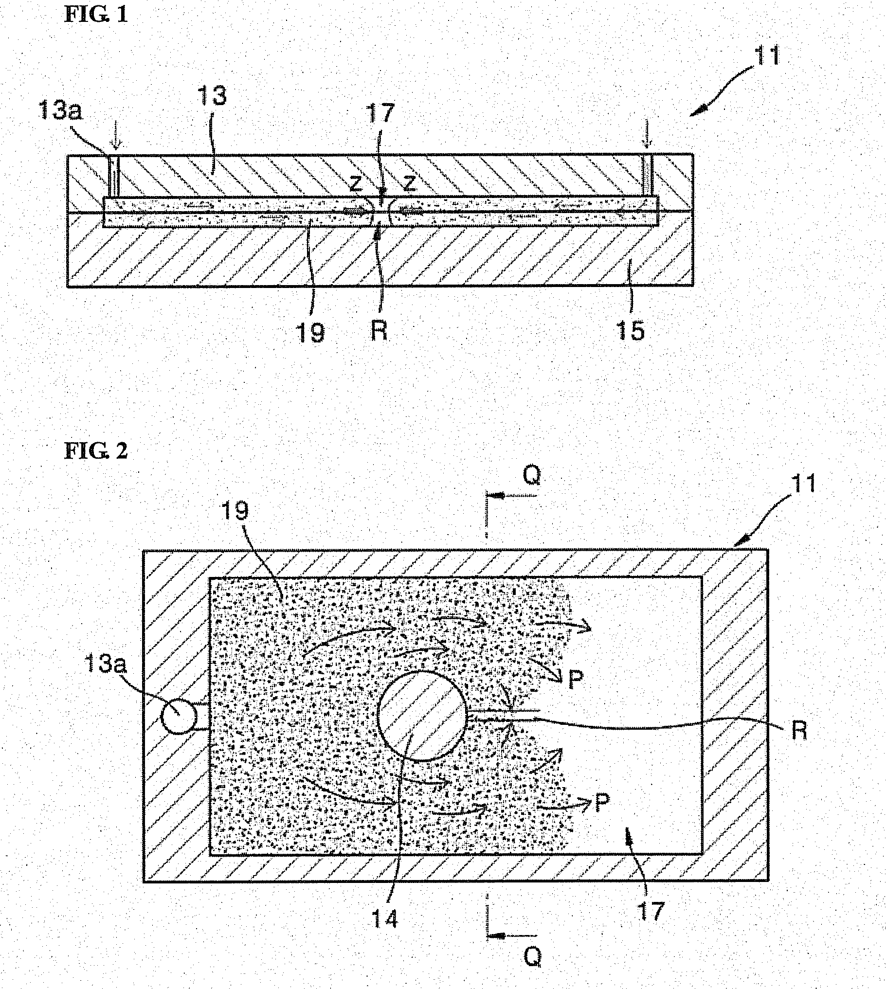
The position at which the molten resin having different flows meet as described above is referred as a weldline R. Since unlike the other portions a flow of the resin is not smooth at a vicinity of the weldline, various phenomena which are not desirable are occurred which is likely to result in generation of a defect in product.
The problem resulted from the weldline is much significant in a case that the molten resin is mixed with pigments for expressing a texture to a product.
Such joining results in the same problem as that occurred when the two flows (which are flowed in through different gates) meet as described through FIG. 1.

Method used


Image

  • Injection mold having shearing flow making part
  • Injection mold having shearing flow making part
  • Injection mold having shearing flow making part

Examples


first embodiment

[0049]FIG. 7 is a structural view schematically illustrating an injection mold device having a shear flow making part according to the present invention.

[0050]Referring to the drawing, the injection mold device according to the first embodiment includes a mold 41 for manufacturing a plate shaped product (reference symbol B in FIG. 14), a roller 49 installed in an inside of the mold 41, and a driving part for driving the roller 49.

[0051]The mold 41 is constructed with a core plate 45 and a cavity plate 43 which is fitted on an upper portion of the core plate 45, and gates 43a for injecting molten resin into a cavity 47 of the mold are provided at both sides of the cavity plate 43. The gates 43a are located the most appropriate position considering a flow speed, flow length or so on of the molten resin.

[0052]Meanwhile, the roller 49 is a round rod type member which has a predetermined diameter and some portion of an outer peripheral surface of the roller is protruded to the cavity 47 ...

second embodiment

[0056]FIG. 8 is a structural view schematically illustrating an injection mold device having a shear flow making part according to the present invention, and there is an advantage that an effect of shear flow can be maximized in comparison with a difficulty of manufacturing parts since a whole surface of a wide moving surface belt 50 instead of the roller in FIG. 7 is slightly protruded and moved.

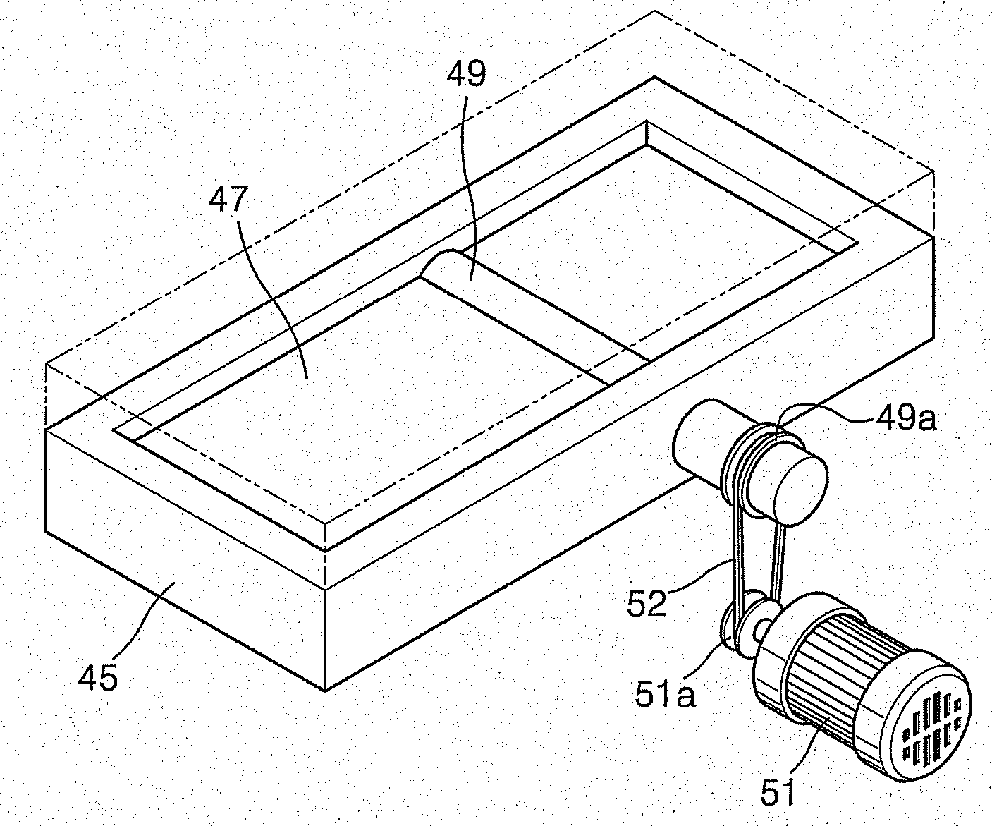
[0057]FIGS. 9 and 10 are partial perspective views illustrating the injection mold device shown in FIGS. 7 and 8, in which a power transmitting connection between the roller 49 and the motor 51 is exemplary illustrated.

[0058]As shown, the roller 49 is rotatively installed at the core plate 45. It is as same as the above description that the some portion of the outer peripheral surface of the roller 49 is protruded t o the upper portion of the core plate 45.

[0059]Particularly, one end portion of the roller 49 extends to a side portion of the core plate 45 and a pulley 49a is secured to the e...

third embodiment

[0067]Referring to FIG. 15, the core plate 57 of the injection mold device is provided with multiple rollers 49. The four rollers 49 are rotated at a same rotational speed by the single motor 51. The rotational speed (a rotational direction is also included in the rotational speed) of the roller 49 is adjustable by the controller 53.

[0068]In addition, the power transmitting connection between each roller 49 and the motor 51 may be implemented by any conventional power coupling. Further, an operating time of the roller 49 is same as that in the first embodiment.

[0069]FIGS. 16 and 17 are views for explaining the operation of the injection mold device shown in FIG. 15.

[0070]As shown, the multiple rollers 49 are protruded from the inward facing surface of the core plate 57 to the upper portion. Each roller 49 makes the molten resin, which is filled in the cavity 47 and in contact with the outer peripheral surface of the roller, to flow viscously in the direction of the arrow X so that ...


PUM

PropertyMeasurementUnit
viscosityaaaaaaaaaa
shearing forceaaaaaaaaaa
structureaaaaaaaaaa

Abstract

The present invention relates to an injection mold device having a shear flow making part. The device comprises an injection mold provided with a cavity in which molten resin mixed with predetermined pigments is filled, a shearing force making part installed in the injection mold, some portion thereof being exposed to the cavity to be in contact with the molten resin injected into the cavity and driven by external power to cause the molten resin in contact with the surface thereof to generate shear flow by a viscosity thereby adjusting locations of the pigments within the molten resin; and a driving part for driving the shearing force making part.The injection mold device according to the present invention is capable of solving a problem due to poor orientation and lack of content of the pigments at a vicinity of the weldline thereby manufacturing a high quality product by generating a viscous flow in the molten resin located at a weldline generation area in an inside of an injection mold and thus adjusting location of the pigments mixed in the molten resin in the corresponding area.

Description

[0001]This application claims the benefit of the filing date of Korean Patent Application No. 10-2006-0013694 filed on Feb. 13, 2006 in the Korean Intellectual Property Office, the disclosure of which is incorporated herein in its entirety by reference.TECHNICAL FIELD[0002]The present invention relates to an injection mold device having a shear flow making part.BACKGROUND ART[0003]In order to add textures, e.g. a metallic, a pearl, a marble texture or so on, on a surface of a synthetic resin product, it is known a method in which resin material is mixed with a variety of pigments for expressing the textures previous to be injection molded. The method has advantages that compared to a method of adding spray coating or painting process to a conventional non-textural surface of a synthetic resin product, a manufacturing cost is much lower and there is no environmental trouble in relation to the coating or painting process.[0004]Meanwhile, in the method of mixing molten resin with the p...

Claims


Application Information

Patent Timeline
Patent Type & Authority Patents(United States)
IPC IPC(8): B29C45/16
CPCB29C45/0025B29C45/0013B29C2045/0031B29K2995/002B29C45/46B29C45/53
Inventor KIM, WORL-YONGKIM, SUN-WOOLEE, EON-SEOK
Owner LG CHEM LTD
Learn More