
Battery determination system for battery-powered devices

a technology of battery determination system and electronic device, which is applied in the direction of secondary cell charging/discharging, alarms, transmission, etc., can solve the problems of not being able to distinguish between ordinary batteries, and additional contact points in the housing. not only an extra cos

Active Publication Date: 2008-10-21
AKG ACOUSTICS
View PDF29 Cites 18 Cited by
  • Summary
  • Abstract
  • Description
  • Claims
  • Application Information

AI Technical Summary

Benefits of technology

"This patent describes a system that can detect if a battery pack or regular batteries are installed in a battery-powered device. The system uses a center contact to measure the voltage in the battery shaft and make contact with the battery pack to determine if it is installed. The system can also determine if the battery pack is connected to the device or a charger unit. The system can enter different modes based on the type of battery pack or charger unit installed. The technical effect of this patent is to provide a reliable way to detect the type of battery pack or charger unit installed in a battery-powered device and ensure proper functionality."

Problems solved by technology

However, this device does not discriminate between ordinary batteries that are individually inserted into the device and the battery packs that might hold the ordinary batteries.
The bus systems, because of their location within the system, may exhibit or produce interference radiation, posing a problem for many applications.
Another problem may involve additional contacts between the battery pack and the device.
The additional contact points in the housing represent not only an extra cost, but may present problems because of the additional contacts and openings in the battery shaft area.
However, it has not solved the problem where different types of rechargeable batteries have been incorporated or where the quality of the batteries in use varies.

Method used


Image

  • Battery determination system for battery-powered devices
  • Battery determination system for battery-powered devices
  • Battery determination system for battery-powered devices

Examples


Embodiment Construction

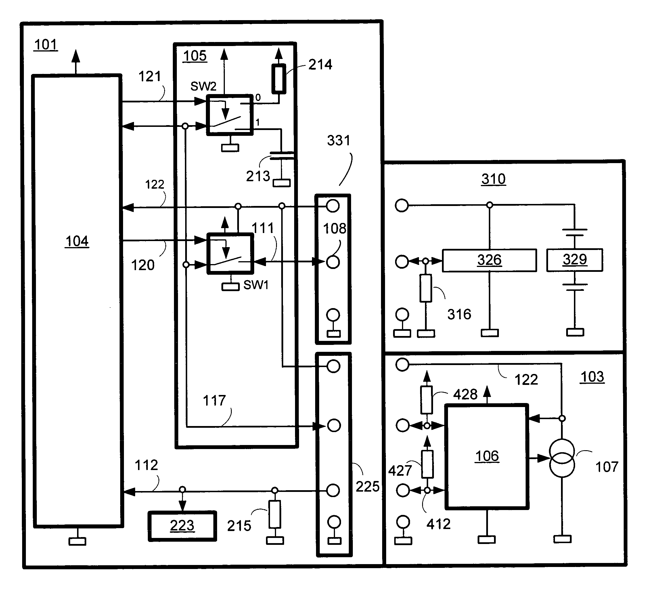
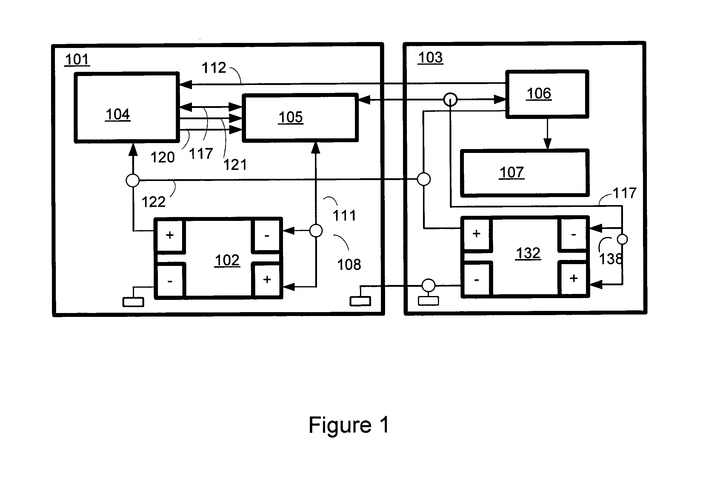
[0022]FIG. 1 is a block diagram of a battery-powered device 101 with an attached charger unit 103. The battery-powered device 101 may be a laptop computer, camera, microphone, headset, dictation machine, cell phone, power tool, or any other battery-powered device that is known or that which becomes known. Also attached to the battery-powered device is a battery shaft 102. A battery unit such as an ordinary battery, a storage (rechargeable) battery, or a battery pack may be inserted into battery shaft 102. A battery unit may contain multiple batteries or battery cells. The battery shaft 102 may be a slot for inserting individual batteries or a battery pack. The battery pack is a smart battery pack that contains electronics for communicating with the battery-powered device 101. Although individual ordinary batteries and / or cells may be included in a holder that is sometimes referred to as a battery pack, such a battery pack functions here as an ordinary battery.

[0023]The battery-power...


PUM

PropertyMeasurementUnit
voltageaaaaaaaaaa
voltageaaaaaaaaaa
voltageaaaaaaaaaa

Abstract

This system provides a method for determining whether ordinary battery cells, a battery pack, and / or a charger unit are attached to a portable electronic device. The system provides a center contact in a battery shaft that contacts a battery pack or a point on an individual battery and allows the device regulation unit to measure the voltage at that point. If the voltage is below a particular threshold, then the system determines that a battery pack may be inserted in the battery shaft and the portable electronic unit enters a battery pack mode. If the voltage is above the threshold voltage, then the portable electronic device enters the battery operation mode. If a voltage transition is sensed on the DEVICE START line, the portable electronic device determines that the charger is installed and the portable electronic device enters the appropriate mode.

Description

PRIORITY CLAIM[0001]This application claims priority under 35 U.S.C. § 119(a)-(d) to European Patent Application No. 03450225.2, filed Oct. 7, 2003, and Austrian Patent Application A 52 / 2004, filed on Jan. 16, 2004, which are incorporated herein by reference.BACKGROUND OF THE INVENTION[0002]1. Technical Field[0003]The present invention relates to battery-powered electronic devices that operate and receive power from batteries, battery packs and charger units and determine whether batteries or battery packs are inserted in the battery-powered device.[0004]2. Related Art[0005]Many electronic devices have become portable enabling their users to remain mobile while receiving the benefits of the portable device. These electronic devices generally require batteries or battery cells to supply the required power for operation, and may include digital cameras, camcorders, wireless microphones, laptop computers, cell phones, and power tools. Many of these devices may have a display that indic...

Claims


Application Information

Patent Timeline
Patent Type & Authority Patents(United States)
IPC IPC(8): H02J7/00G01N27/416G08B21/00H04B1/38G03B17/02G03B17/56H01M10/44H01M10/46H01M10/48
CPCH02J7/0036H02J7/0029
Inventor BRENNER, ERICH
Owner AKG ACOUSTICS
Learn More