
Phase split structure of multiphase superconducting cable

a superconducting cable and split structure technology, applied in the direction of superconducting magnets/coils, coupling device connections, magnetic bodies, etc., to achieve the effect of minimizing or nullifying the magnetic field

Inactive Publication Date: 2008-10-21
SUMITOMO ELECTRIC IND LTD
View PDF13 Cites 3 Cited by
  • Summary
  • Abstract
  • Description
  • Claims
  • Application Information

AI Technical Summary

Benefits of technology

[0009]An object of the present invention is to provide a phase split structure of a multiphase superconducting cable to minimize or nullify a magnetic field that could be generated outside a plurality of cable cores.
[0012]If respective shield layers of the cable cores of the multiphase superconducting cable are connected to each other via the ground, the connection resistance between the shield layers is high. In such a case, there arises a difficulty in generating a magnetic field by each of respective shield layers of the cable cores that can cancel out a magnetic field generated from the superconductor of each cable core. The present invention thus connects respective shield layers of the cable cores to each other with an electrically-conductive member having a lower connection resistance instead of connecting the shield layers via the ground which results in a high connection resistance.
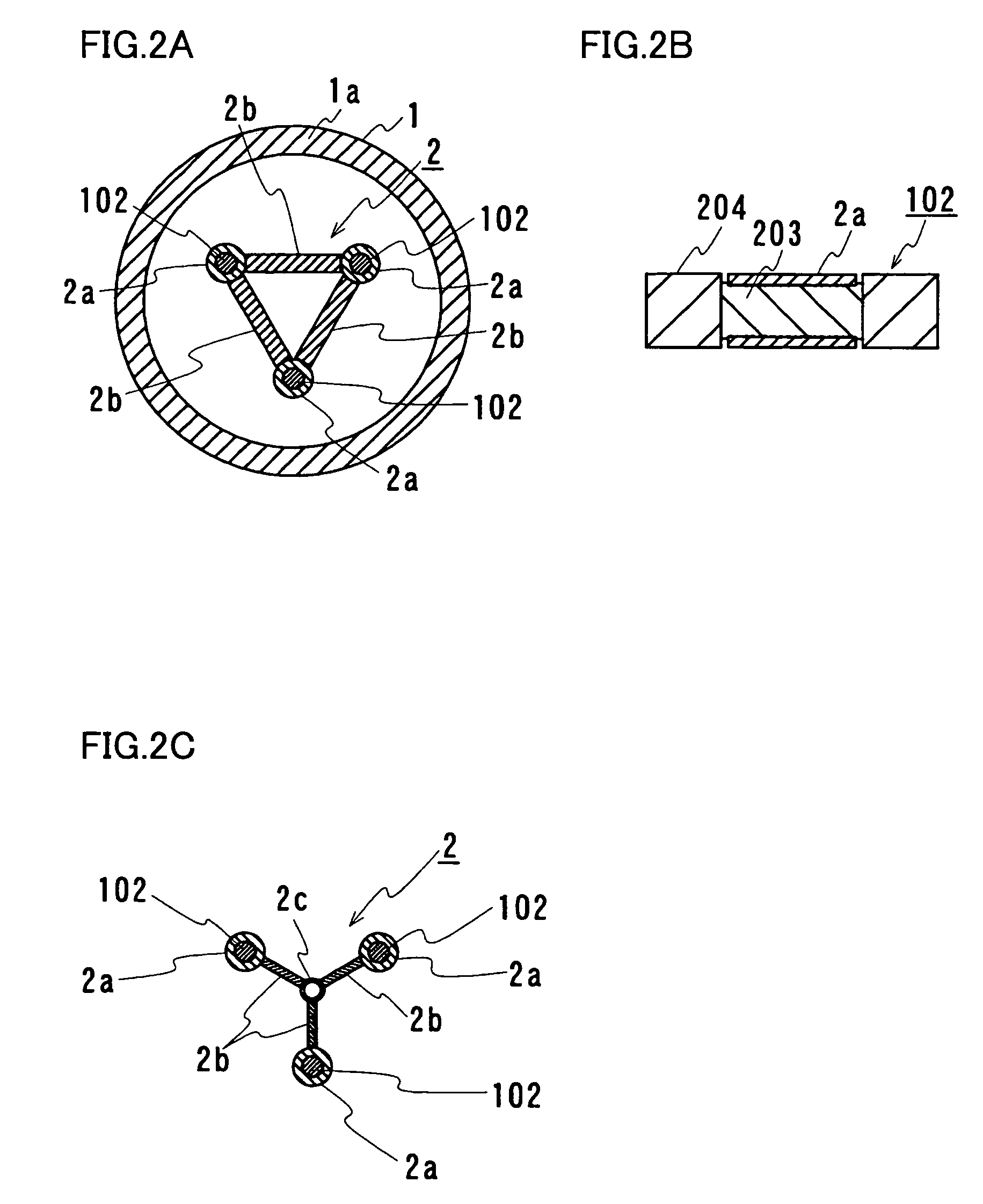
[0017]According to the present invention, respective shield layers of the cable cores housed in the splitter box are connected to each other by means of a particular connecting portion, specifically, an electrically-conductive connecting portion formed of an electrically-conductive material. The electrically-conductive material is preferably such a material as copper or aluminum (both having a specific resistance at 77K: ρ=2×10⁻⁷ Ω·cm). These metals each have an electrical resistance which is low even at a temperature close to the temperature of a refrigerant of the superconducting cable, for example, the temperature of liquid nitrogen if it is used as the refrigerant. The conductive connecting portion may connect at least respective parts, with respect to the longitudinal direction, of respective shield layers of the cable cores housed in the splitter box. The connecting portion may be shaped in a manner that the connecting portion contacts at least respective parts, with respect to the circumferential direction, of respective shield layers of the cable cores and can connect respective shield layers of the cable cores to each other. If respective shield layers of the cable cores are each formed of a plurality of superconducting strands, the connecting portion is preferably shaped in such a manner that the connecting portion can be electrically connected to all of the constituent superconducting strands. For example, the connecting portion is shaped to have a combination of cylindrical members each capable of covering the periphery of each of respective shield layers of the cable cores and coupling members coupling the cylindrical members to each other. In particular, the coupling member is preferably a flexible member. More specifically, the coupling member is formed of a braided material. The flexible coupling member can be used to accommodate to any movement of each core that occurs upon contraction caused by cooling. The flexibility of the coupling member provides excellent workability in terms of assembly in a limited space like the inside of the splitter box and can absorb any dimensional error resultant from the assembly work.
[0020]The conductive connecting portion may be provided at an arbitrary position of each of the cable cores within the splitter box. If the conductive connecting portion is provided at a position relatively closer to the termination of the split cable (hereinafter split termination), the cable cores are spaced further apart from each other and thus the distances between the cable cores increase. In such a case, the workability in attaching the connecting portion is improved and thus this method is preferable. In contrast, if the conductive connecting portion is provided at a position relatively closer to the assembly portion, the cable cores are not substantially spaced further apart and thus the distances therebetween are smaller. In this case, the conductive connecting portion can be made compact and the part of the splitter box that is located closer to the split termination can be made smaller since the connecting portion is located away from the split termination. In other words, the splitter box can be made more compact.

Problems solved by technology

In such a case, there arises a difficulty in generating a magnetic field by each of respective shield layers of the cable cores that can cancel out a magnetic field generated from the superconductor of each cable core.

Method used


Image

  • Phase split structure of multiphase superconducting cable
  • Phase split structure of multiphase superconducting cable
  • Phase split structure of multiphase superconducting cable

Examples


first embodiment

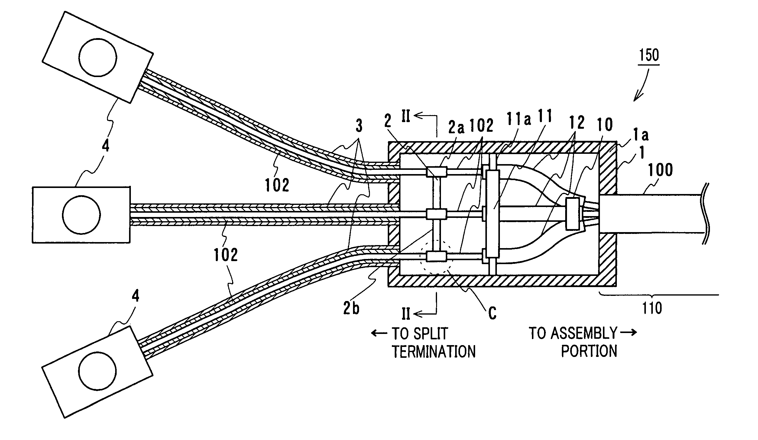
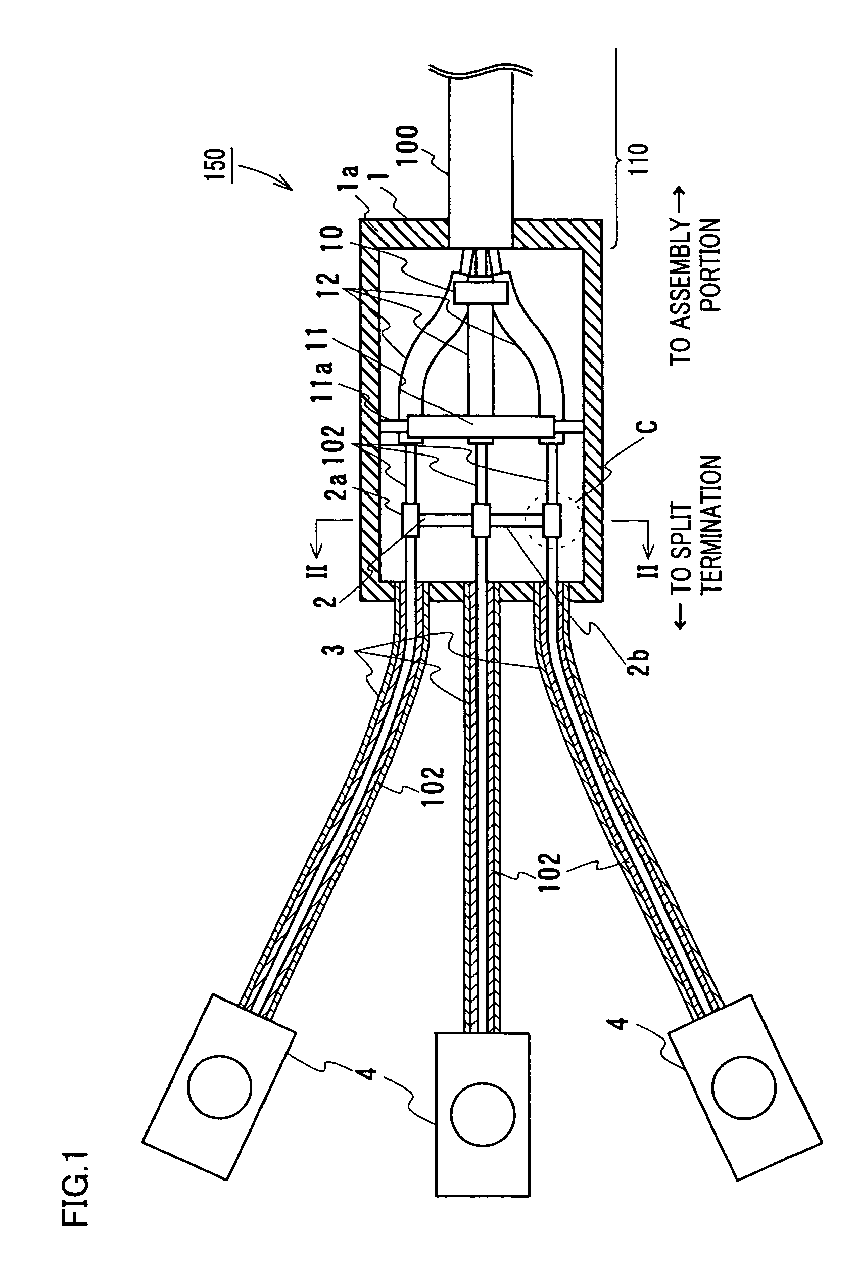
[0029]This embodiment is described in connection with an example of a phase split structure of a three-phase superconducting cable 100 having three cable cores 102 as shown in FIG. 1.

[0030]Referring to FIG. 1, a phase split structure 150 of the multiphase superconducting cable of this embodiment includes three cable cores 102 each having a shield layer provided around a superconductor, a splitter box 1 housing cable cores 102 in a state in which cable cores 102 extending from an assembly portion 110 where three cable cores 102 are assembled into the superconducting cable are spaced apart from each other, and an electrically-conductive connecting portion 2 connecting respective shield layers of cable cores 102 to each other in splitter box 1.

[0031]Three-phase superconducting cable 100 of this embodiment has the same structure as that shown in FIG. 4. Specifically, referring to FIG. 4, three-phase superconducting cable 100 is structured by twisting three cable cores 102 and housing th...

second embodiment

[0044]Referring to FIGS. 3A and 3B, a phase split structure 160 of a multiphase superconducting cable in this embodiment is basically similar in structure to phase split structure 150 of the multiphase superconducting cable in the first embodiment shown in FIG. 1, and differs therefrom in that an electrically-conductive connecting portion 2′ is provided relatively closer to assembly portion 110 with respect to second holding tool 11, which is described in detail below. Here, the terminal portions are not shown in FIG. 3A.

[0045]Conductive connecting portion 2′ of the second embodiment includes, as shown in FIG. 3B, cylindrical members 2a′ covering respective peripheries of shield layers respectively of a plurality of cable cores 102 as well as a coupling member 2b′ coupling these cylindrical members 2a′ to each other. Cylindrical members 2a′ of this embodiment, like those of the first embodiment, are each formed of a pair of semi-arc members of copper. Semi-arc members of cylindrical...

third embodiment

[0049]Referring to FIGS. 1 and 3A, the first and second embodiments have been described in connection with the structure having thermal insulation pipe 3 of stainless, which is a high-resistance material, provided around the periphery of each of cable cores 102 extending from splitter box 1. In this embodiment, thermal insulation pipe 3 is made of an insulation material of FRP (Fiber Reinforced Plastics). With the phase split structure of the superconducting cable of this embodiment, even if a leakage magnetic field is generated around cable cores 102 in the region from conductive connecting portion 2, 2′ to the terminal portions (see FIG. 1), it is unlikely that eddy current occurs since thermal insulation pipes 3 provided around respective peripheries of cable cores 102 extending from the splitter box are made of the insulation material. Any loss due to the eddy current can thus be reduced more effectively.

[0050]As heretofore discussed, with the phase split structure of the presen...


PUM

PropertyMeasurementUnit
temperatureaaaaaaaaaa
superconductingaaaaaaaaaa
electrically-conductiveaaaaaaaaaa

Abstract

A phase split structure of a superconducting cable includes three cable cores each having a shield layer provided around a superconductor, a splitter box housing the three cable cores extending from an assembly portion where the three cable cores are assembled into the cable, in a state in which the cable cores are spaced apart from each other, and an electrically-conductive connecting portion connecting respective shield layers of the cable cores to each other within the splitter box. In this way, occurrence of a large magnetic field outside the cable cores can effectively be reduced.

Description

BACKGROUND OF THE INVENTION[0001]1. Field of the Invention[0002]The present invention relates to a split structure for splitting a multiphase superconducting cable constructed of a plurality of cable cores into respective segments containing the cores. In particular, the present invention relates to a phase split structure of a multiphase superconducting cable to minimize or nullify a magnetic field that could be generated outside each cable core.[0003]2. Description of the Background Art[0004]As one of superconducting cables that have been produced using a superconductor formed of a Bi-based high-temperature superconducting tape for example, a multiphase superconducting cable of multicore type that is produced by assembling a plurality of cable cores into one unit is under development.[0005]Referring to FIG. 4, this superconducting cable 100 includes three cable cores 102 twisted and housed in a thermal insulation pipe 101. Thermal insulation pipe 101 has an outer pipe 101a and an ...

Claims


Application Information

Patent Timeline
Patent Type & Authority Patents(United States)
IPC IPC(8): H01B12/00H01R43/00H01B12/02H01R4/68H01R9/03H01R13/658H02G15/076H02G15/08H02G15/34
CPCH01R9/032H02G15/34H01R4/68H01R13/65807Y02E40/648H01R13/65912Y02E40/60H01R13/6598
Inventor MASUDA, TAKATOYUMURA, HIROYASUTAKAHASHI, YOSHIHISAMATSUO, KIMIYOSHIHONJO, SHOICHIMIMURA, TOMOO
Owner SUMITOMO ELECTRIC IND LTD
Learn More