Phase split structure of multiphase superconducting cable
- Summary
- Abstract
- Description
- Claims
- Application Information
AI Technical Summary
Benefits of technology
Problems solved by technology
Method used
Image
Examples
first embodiment
[0034
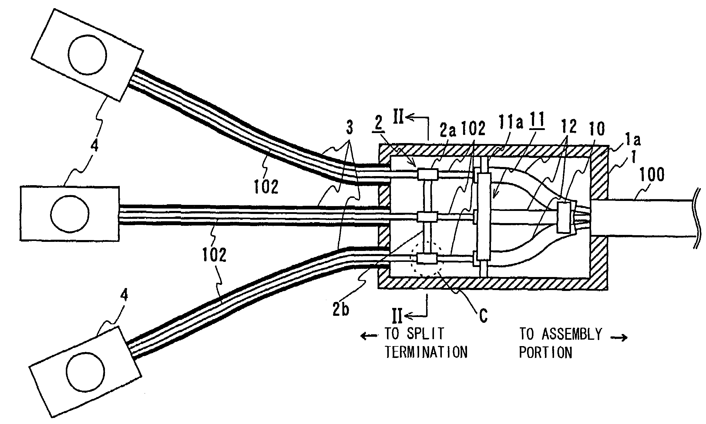
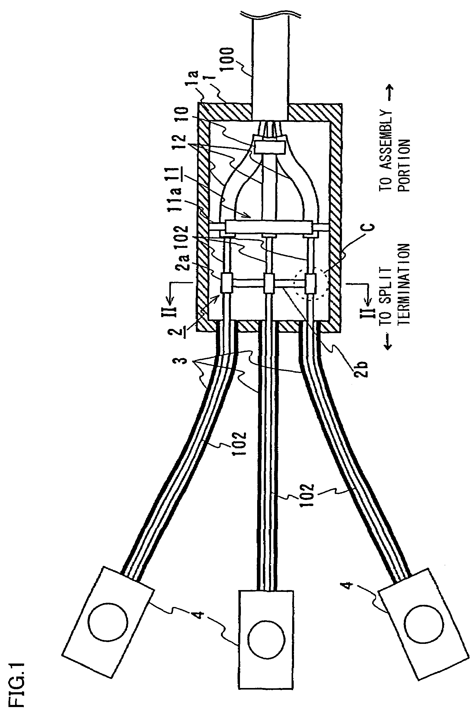
[0035]This embodiment and a second embodiment described hereinafter are described in connection with an example of a phase split structure of a three-phase superconducting cable 100 having three cable cores 102 as shown in FIGS. 1 and 4.
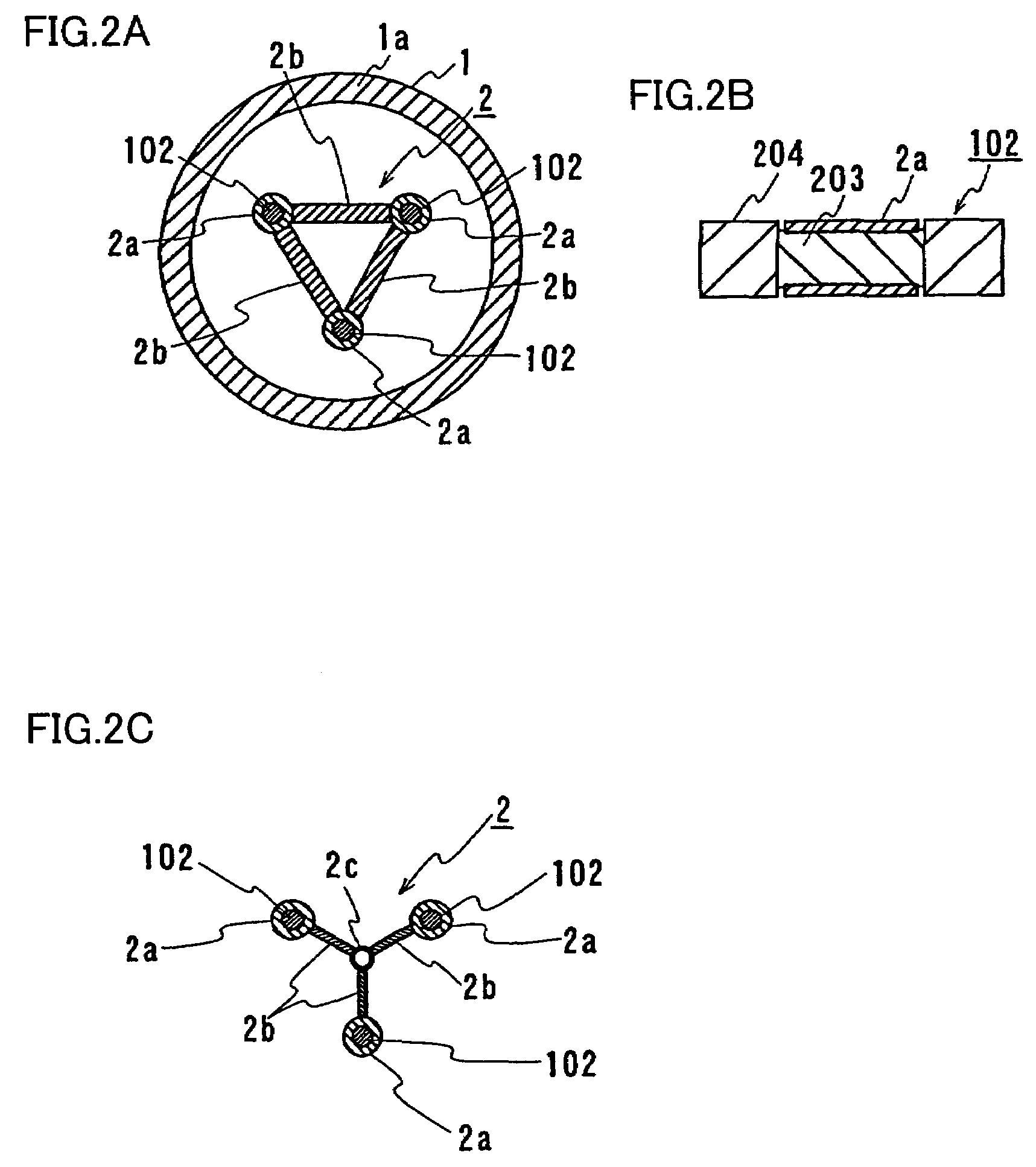
[0036]Referring to FIG. 1, the present phase split structure includes three cable cores 102 each having a shield layer provided around a superconductor, a splitter box 1 housing cable-cores 102 in a state in which cable cores 102 extending from an assembly portion where three cable cores 102 are assembled into the superconducting cable are spaced apart from each other, and a shield connecting portion 2 connecting respective shield layers of cable cores 102 to each other in splitter box 1.
[0037]Three-phase superconducting cable 100 of this embodiment has the same structure as that shown in FIG. 5. Specifically, three-phase superconducting cable 100 is structured by twisting three cable cores 102 and housing them in thermal insulation pipe 101, th...
second embodiment
[0051
[0052]In FIG. 4A the terminal portion is not shown. The present phase split structure basically has a structure similar to that described in the first embodiment except that a shield connecting portion 2′ is provided relatively closer to an assembly portion with respect to second holding tool 11, which is described in detail below.
[0053]Shield connecting portion 2′ of this embodiment includes, as shown in FIG. 4B, cylindrical members 2a′ covering respective peripheries of shield layers respectively of a plurality of cable cores 102 as well as a coupling member 2b′ coupling these cylindrical members 2a′ to each other. Cylindrical members 2a′ of this embodiment, like those of the first embodiment, are each formed of a pair of semi-arc members of copper. Semi-arc members of cylindrical member 2a′ are provided around a corresponding shield layer exposed by partially removing protection layer 204 of cable core 102 and are connected with bolts to cover cable core 102. Cylindrical mem...
third embodiment
[0058
[0059]In the first and second embodiments a superconducting wire formed in a power in tube process, i.e., a superconductor formed of a superconducting phase and a metal has been used to implement a shield connecting portion. In this embodiment will be described an example employing a shield connecting portion that has a basic structure similar to that described in the first embodiment and employs a superconductor formed only of a superconducting phase. More specifically, it corresponds to the FIG. 1 example with superconducting wire 23 (see FIG. 3B) formed of a bulk superconductor of Bi2223 oxide superconducting phase. In this embodiment the bulk superconductor is used in the form of a bar.
[0060]As described in this embodiment, the shield connecting portion includes a coupling member formed of a bulk superconductor that does not have silver or other similar metal interposed. Furthermore, the bulk superconductor is not arranged on a copper plate or the like longitudinally. This ...
PUM
 Abstract
Description
Claims
Application Information
 - R&D
- Intellectual Property
- Life Sciences
- Materials
- Tech Scout
- Unparalleled Data Quality
- Higher Quality Content
- 60% Fewer Hallucinations
Browse by: Latest US Patents, China's latest patents, Technical Efficacy Thesaurus, Application Domain, Technology Topic, Popular Technical Reports.
© 2025 PatSnap. All rights reserved.Legal|Privacy policy|Modern Slavery Act Transparency Statement|Sitemap|About US| Contact US: help@patsnap.com


