
Imprint method for manufacturing micro capacitive ultrasonic transducer

a manufacturing method and ultrasonic transducer technology, applied in electrical transducers, mechanical vibration separation, instruments, etc., can solve the problems of reducing the bandwidth and sound pressure of the bandwidth affecting the efficiency of the piezoelectric transducer, and still ejecting the piezoelectric transducer, etc., to achieve cost reduction

Active Publication Date: 2008-10-21
IND TECH RES INST
View PDF2 Cites 5 Cited by
  • Summary
  • Abstract
  • Description
  • Claims
  • Application Information

AI Technical Summary

Benefits of technology

This method enables large batch manufacturing of micro capacitive ultrasonic transducers with improved sensitivity, uniformity, and cleanliness, overcoming the limitations of traditional transducers by precisely controlling the size and shape of oscillation cavities and reducing contamination, leading to enhanced inspection efficiency.

Problems solved by technology

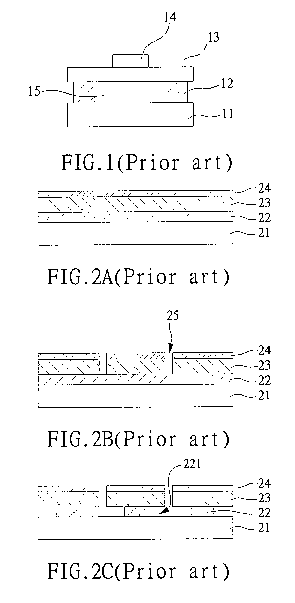
However, the piezoelectric transducer still exit some disadvantages, for example the cost of such piezoelectric transducer is too high, and the oscillation of the crystal lattice will easily debase the bandwidth and the sound pressure.
Moreover, the difference between the impedances of the piezoelectric material and that of the air is so large as to cause the unmatched phenomenon thus resulting in large reflection of the sonic signals in the contact interface and diminish the inspection efficiency.
In addition, for the limitation of the resolution and the bandwidth, the piezoelectric transducer is hardly to be used for the precise inspection in nano-level.
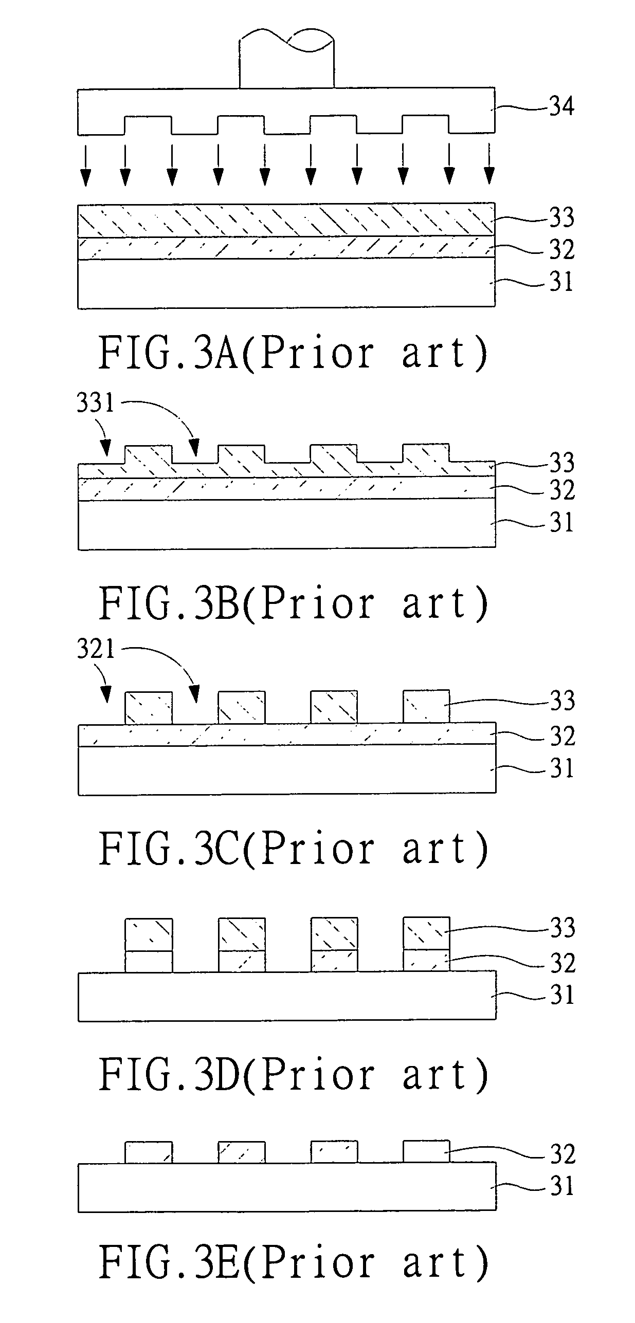
However, such method is hardly to control the precise shape of the oscillation cavities and cannot provide the check mechanism.
It only depends on the experience so that many vibrations in the process, such as the variation of the etching solution concentration, will very easily cause the variation of the geometrical size of the oscillation cavities 221 further affecting the character of the whole transducers.

Method used


Image

  • Imprint method for manufacturing micro capacitive ultrasonic transducer
  • Imprint method for manufacturing micro capacitive ultrasonic transducer
  • Imprint method for manufacturing micro capacitive ultrasonic transducer

Examples


first embodiment

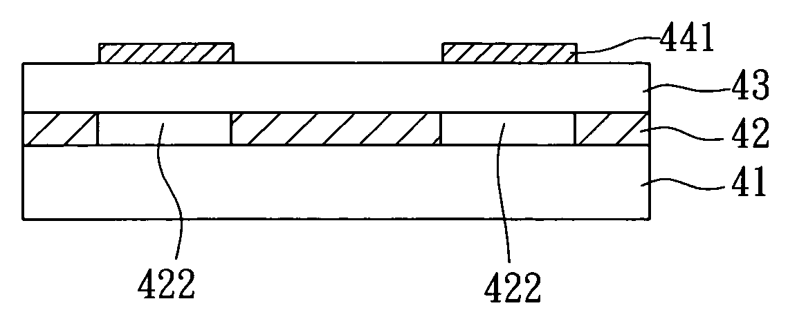
[0045]FIG. 4A to FIG. 4G are the schematic views showing the present invention. As shown in the figures, the substrate 41 doped with impurity for electric conductivity is provided for the lower electrode of the ultrasonic transducer. In the preferable embodiment, a plurality of lower electrode plates can be formed on the substrate 41; wherein between any two of the adjoining lower electrode plates are linked by a conductor line. Then, a support film layer 42 is formed on the substrate 41. To operate in the nanoimprint technology, the material of the support film layer 42 has to be flexible polymer such as PMMA. In order to improve the sensitivity of the ultrasonic transducer, the support film layer 42 used to be the wall of the oscillation cavities of the transducer is better to be controlled as thin as possible. Further, a mold 51 with a patterned surface 511 is provided, and wherein the patterned surface 511 has an array pattern 512 with projections and recesses arranged in order....

second embodiment

[0059]Moreover, the formation of the upper electrode plates both in the first and the second embodiment can be carried out after the polymer film stuck onto the support film layer. In other words, after forming a plurality of recessions of the support film layer on the substrate, the polymer film can be struck onto the support film layer in advance thus sealing the plurality of recessions to become a plurality of the closed cavities for micro capacitive ultrasonic transducer. Finally, a plurality of the upper electrode plates corresponding to the closed cavities is formed on the polymer film thus completing a plurality of the micro capacitive ultrasonic transducers.

[0060]Although the present invention has been described with reference to a preferred embodiment, it should be appreciated that various modifications and adaptations can be made without departing from the scope of the invention as defined in the claims.

[0061]In summary, from the structural characteristics and detailed dis...


PUM

PropertyMeasurementUnit
conductiveaaaaaaaaaa
flexibleaaaaaaaaaa
ultrasonic inspectionaaaaaaaaaa

Abstract

The present invention relates to an imprint method for manufacturing micro capacitive ultrasonic transducer, which uses a mold with a particularly patterned surface to imprint into a flexible material thus forming the oscillation cavities of the ultrasonic transducer. Such imprint method not only realizes the volume manufacturing and reduces the cost, but also can precisely control the geometrical size of the oscillation cavities and thus shorten the distance between the upper and the lower electrodes to the micro / nano level, largely improving the sensitivity of the transducer. Moreover, the present invention further changes the procedure for manufacturing micro capacitive ultrasonic transducer of the prior art, which can both save the process steps and overcome the disadvantages in the prior art.

Description

FIELD OF THE INVENTION [0001]The present invention relates to a method for manufacturing ultrasonic transducer, in particular to a method for manufacturing micro capacitive ultrasonic transducer. In detail, the present invention employs the nanoimprint lithography method to manufacture the micro capacitive ultrasonic transducer.BACKGROUND OF THE INVENTION [0002]The technology of ultrasonic inspection has been developed since the World War II. In the beginning, it is used for the national defense and the military affairs. Until 1950s, the ultrasonic inspection technology started to be widely employed on the medical treatments. In the area of the ultrasonic inspection, ultrasonic transducer plays a very important role thus attracting the industry / government / academia to plunge into the research in the past decades, and the related technologies are also getting more and more mature now. Among all the ultrasonic transducers, the piezoelectric transducer was kept the main stream for a lon...

Claims


Application Information

Patent Timeline
Patent Type & Authority Patents(United States)
IPC IPC(8): B44C1/22B06B1/02
CPCB06B1/0292Y10T29/49005Y10T29/49007
Inventor NIEN, CHIN-CHUNGHO, HONG CHENCHANG, MING-WEI
Owner IND TECH RES INST
Learn More