
Methods and apparatus for managing network resources via use of a relationship view

a network resource and relationship view technology, applied in the field of relationship view management methods and apparatus, can solve the problems of inconvenient network management software applications that graphically display physical connectivity among network resources, and inconvenient use of network topology views. achieve the effect of quick identification, easy identification of managed entities, and quick identification

Active Publication Date: 2008-10-14
EMC IP HLDG CO LLC
View PDF4 Cites 69 Cited by
  • Summary
  • Abstract
  • Description
  • Claims
  • Application Information

AI Technical Summary

Benefits of technology

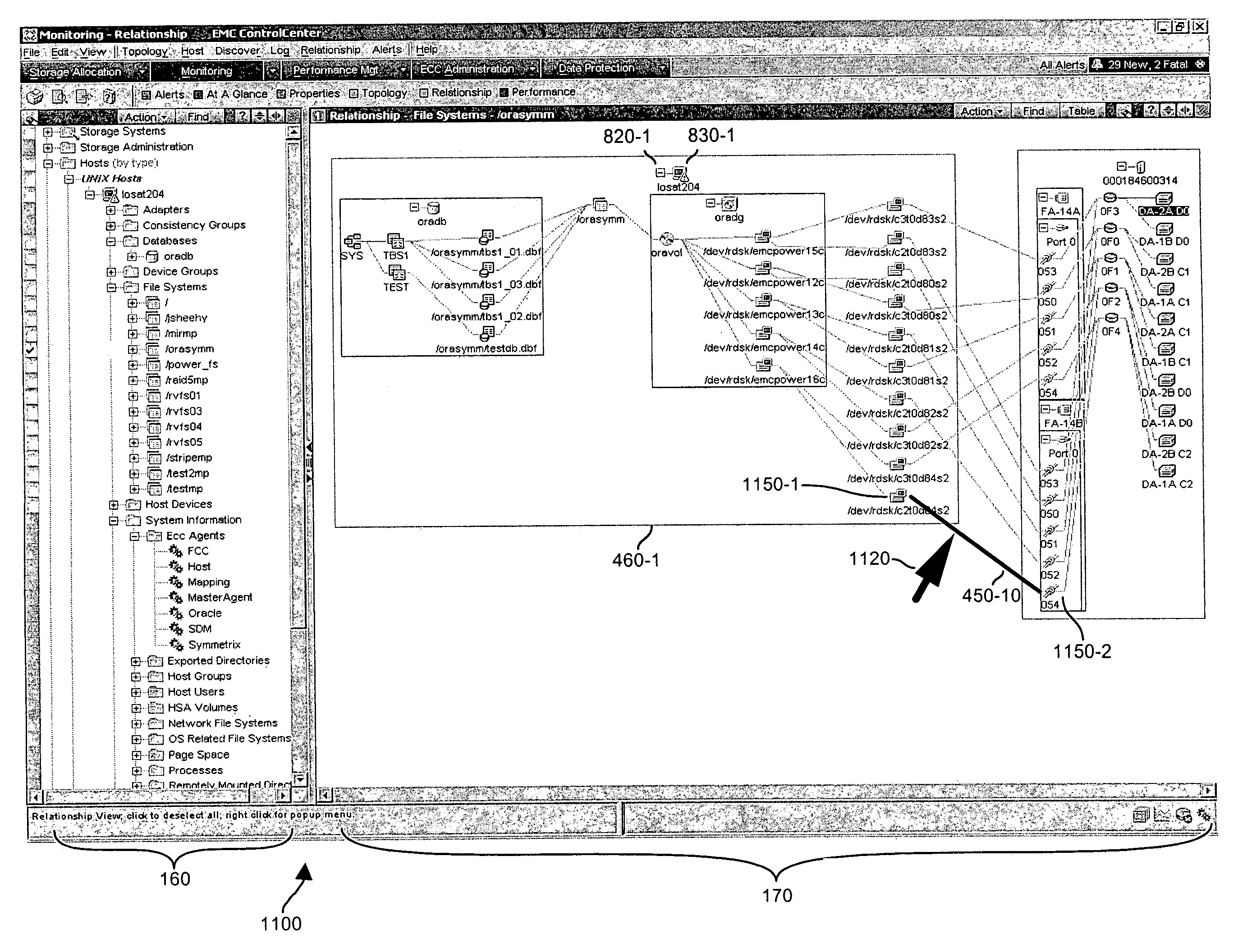
[0016]In one embodiment, the processing device generates a horizontally disposed relationship view of adjacently positioned columns including multiple icons and corresponding relationship paths from the perspective of an icon associated with the selected managed entity. Presenting adjacent columns of icons enables the viewer to quickly identify a group of similar types of managed entities in the storage area network. Presenting relationship paths between the icons spanning from, for example, an icon representing a software entity (such as a DB schema) to a hardware entity (such as a corresponding storage device) enables the viewer of the relationship view to easily identify managed entities related to the selected managed entity.
[0017]In addition to use of icons and corresponding relationship paths to illustrate a sequence of identified relationships, a relationship view may include a container (e.g., a graphical box) encompassing one or multiple icons (or even other containers) to represent another managed entity associated with the storage area network. For example, a container may represent a managed entity such as a database, a group of volumes, a host server, a storage disk, etc. Use of one or multiple containers (or nested containers) in the relationship view along with icons and relationship paths enables the viewer to quickly identify that a group of icons is associated with a particular volume, database, host server, etc.
[0018]One display mode associated with a relationship view involves use of a viewer controlled device (such as a computer mouse) to highlight relationship paths displayed in a corresponding relationship view between icons representing managed entities. The viewer controlled device supports movement of a corresponding cursor (such as an arrow icon) on the display screen. In response to detecting that the cursor is in a vicinity of a given relationship path (as selected by the viewer) or that a user clicks on a relationship path, the processing device highlights (bolds, changes color, distinguishes, . . . ) the given relationship path over others also displayed on a display screen. This feature may be extended to highlight icons, containers and other managed entities displayed in the relationship view when a use clicks on such symbols. Consequently, a viewer may easily identify icons at either ends of the highlighted relationship path even in the presence of many densely displayed relationship paths between other neighboring displayed icons.
[0020]Yet another display mode supported by an embodiment of the invention enables a user to select and display multiple relationship views simultaneously. For example, the processing device may display a first relationship view having a level of detail as selected by a given viewer. From the first relationship view, a user may select a particular icon among many displayed icons and corresponding relationship paths. In response to detecting the user's selection of the particular icon in the first area, the processing device generates a second relationship view in a second area of the display screen. The second relationship view includes a presentation of relationships between a managed entity associated with the particular icon and other associated nearest neighboring managed entities in the storage area network. This display management function enables a user to duplicate a relationship view for the selected entity apart from other unwanted relationship information in the first view. In one embodiment, the processing device generates a second relationship view in response to a user dragging and dropping the particular icon from a first area of the display screen to a second area of a display screen.
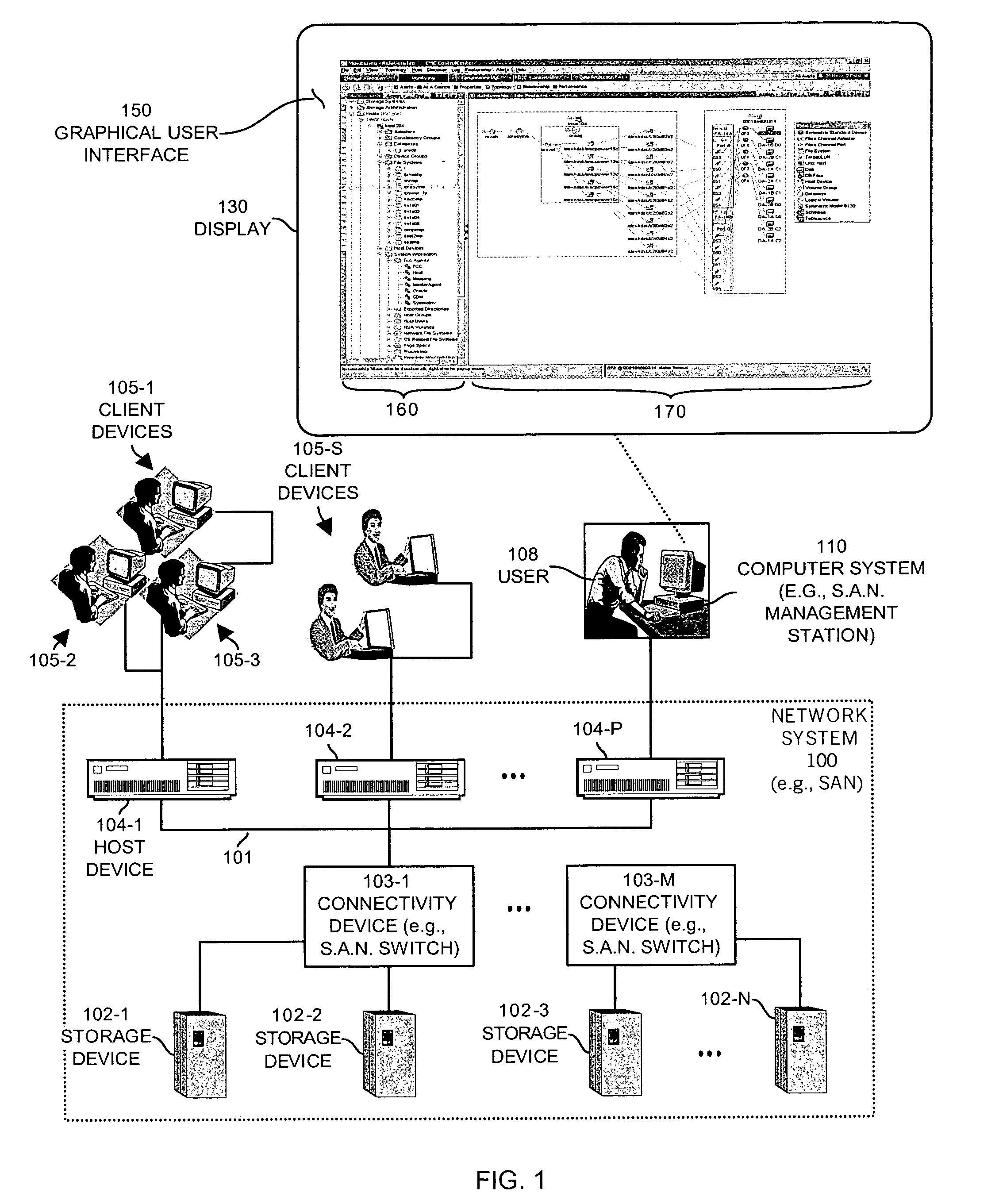
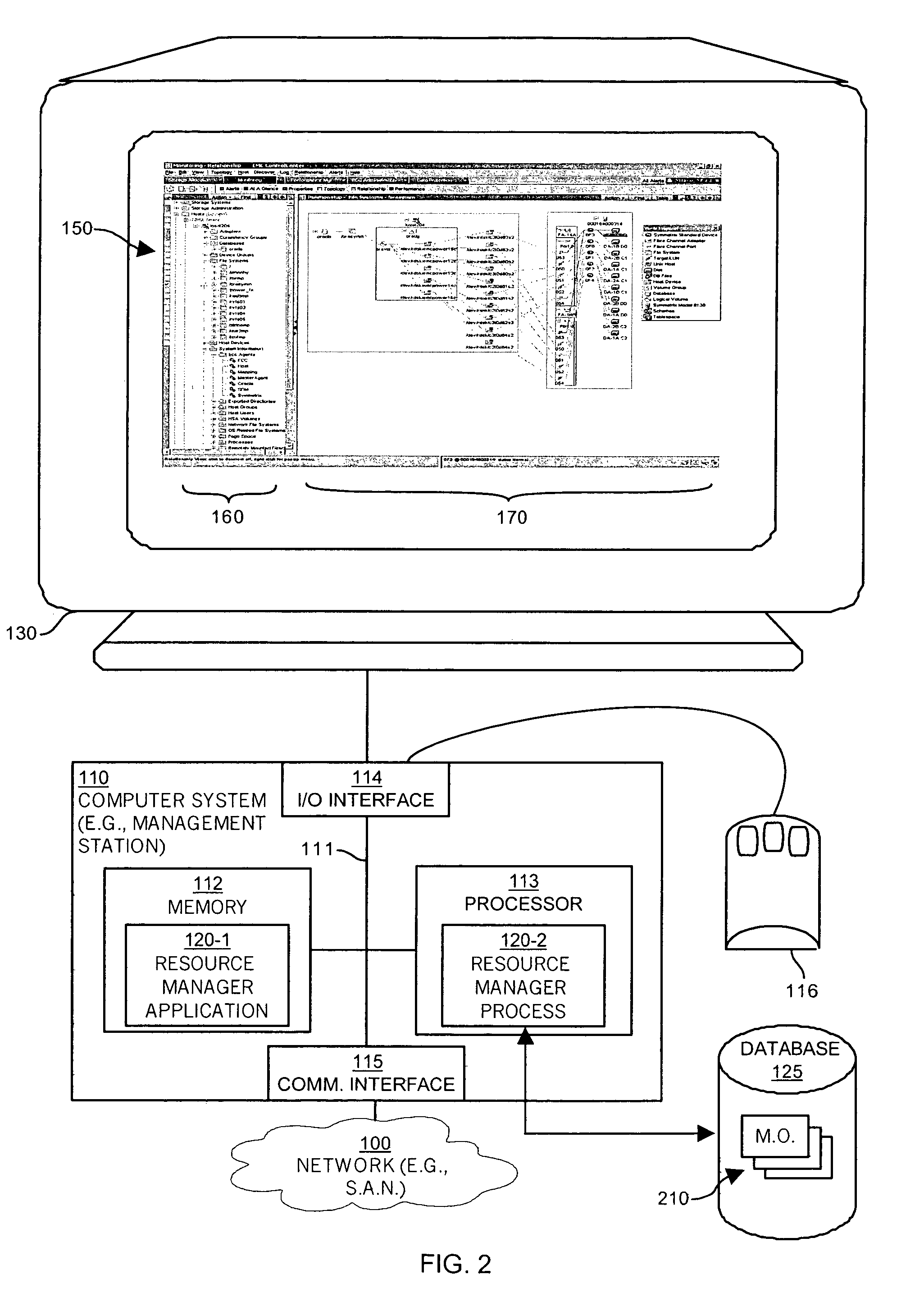
[0021]Other embodiments of the invention include a computerized device (e.g., a host computer, workstation, etc.) configured to support the aforementioned method operations disclosed herein as embodiments of the invention to provide a relationship view and associated resource management operations. In such embodiments, the computerized device includes a display, a memory system, a processor (e.g., a processing device) and an interconnect. The interconnect supports communications among the display, the processor and the memory system. The memory system is encoded with a resource management application that, when executed on the processor, produces a resource management process that includes a graphical user interface produced on the display of the computerized device. The graphical user interface allows the resource management process to perform all of the method embodiments and operations explained herein as embodiment of the invention.

Problems solved by technology

Conventional network management software applications that graphically display physical connectivity among network resources suffer from a variety of deficiencies.
For example, conventional network management software applications do not uniformly present network topology views in a consistent and optimal manner across all hosts, database and storage platforms for ease of use by a user of such software applications.
This conventional technique for displaying a network topology or interconnection of manageable network resources suffer from deficiencies due in large part to a lack of ergonomic considerations.
For example, users typically have a limited ability to visually scan, identify, select and then apply management display commands to specific manageable network resources of interest using conventional network views and supported display functions.
That is, conventional relationship views of managed entities render it difficult (e.g., sometimes due to high density of icons and corresponding relationships) for a user to identify and then select particular managed resources of interest in a network due to the complex graphical layouts that such conventional applications provide.
Furthermore, conventional applications fail to support user friendly management display functions to manage entities that enhance a GUIs usefulness.

Method used


Image

  • Methods and apparatus for managing network resources via use of a relationship view
  • Methods and apparatus for managing network resources via use of a relationship view
  • Methods and apparatus for managing network resources via use of a relationship view

Examples


Embodiment Construction

[0037]Embodiments of the invention include a processing device that generates a relationship view including managed entities associated with a storage area network based on corresponding objects stored in a relational database. For example, a management database tracks relationships among managed hardware and software entities via use of corresponding managed objects. Each managed entity in the storage area network has a corresponding managed object stored in the relational database. Generally, managed objects of a particular type are categorized into one or more tables. The tables are related to one another by foreign key attributes, which indicate relationships between types of managed objects (and thus a relationship between corresponding managed entities). Relationships between the managed objects in the relational database may be generally classified as either association or containment. Association identifies a logical relationship between managed objects. Containment identifi...


PUM


Abstract

A processing device generates a relationship view of managed entities in a storage area network based on objects stored in a relational database. Each managed entity (e.g., file system, database, volume, storage device, etc.) in the storage area network has a corresponding managed object stored in the relational database. Generally, managed objects of a particular type are categorized into one or more tables. Such tables are related to one another by foreign key attributes, which represent relationships between types of managed objects (and thus a relationship between corresponding managed entities). Relationships among the managed objects in the relational database may be generally classified as either association or containment. Association identifies a logical relationship between managed objects. Containment identifies groups of managed objects that are logically associated with each other. The processing device uses these identified relationships to generate the appropriate relationship view for a selected managed entity.

Description

BACKGROUND OF THE INVENTION[0001]Certain conventional computer devices include Graphical User Interfaces (GUI) that enable network managers to graphically manage, control and configure various types of hardware and software resources associated with a corresponding managed storage area network. In one conventional application, a network management application rendering the graphical user interface enables the network manager to graphically select, interact with, and manage local or remote devices and associated software processes operating in the storage area network. More specifically, based on use of the graphical user interface in combination with an input device such as a hand operated mouse and corresponding pointer displayed on a viewing screen, a network manager is able to manage hardware and software entities such as file systems, databases, storage devices, peripherals, network data communications devices, etc. associated with the storage area network. Typically, in such ne...

Claims


Application Information

Patent Timeline
IPC IPC(8): G06F3/00
CPCH04L41/024H04L41/22G06F3/0601G06F2003/0697H04L67/1097G06F2206/1008G06F3/0605G06F3/067G06F3/0655
Inventor MAGDUM, ZAKIR G.FICKIE, KENNETH E.YEHUDA, HANNA
Owner EMC IP HLDG CO LLC
Learn More