
Methods and apparatus for balancing a rotor

a rotor and rotor technology, applied in the field of rotors, can solve the problems of imbalanced load acting on the rotor, affecting the bending moment, so as to facilitate the bending moment at leas

Active Publication Date: 2008-10-14
GENERAL ELECTRIC CO
View PDF4 Cites 39 Cited by
  • Summary
  • Abstract
  • Description
  • Claims
  • Application Information

AI Technical Summary

Benefits of technology

The patent describes a method and system for balancing a rotor of a rotary machine. The system includes sensors to measure load, acceleration, or displacement on the rotor shaft, which is caused by bending moments. By analyzing these measurements, the system calculates the bending moments on the rotor shaft and determines the pitch offset angle of the rotor blades to reduce these moments. This results in a balanced rotor with reduced bending moments on the rotor shaft. The technical effect of this patent is to improve the efficiency and lifespan of rotary machines by reducing bending moments on the rotor shaft.

Problems solved by technology

Imbalanced loading in the rotating frame acting on at least some known rotors may occur due to mass imbalance in the blade set, geometrical irregularities in rotor and / or blade mounting, differences in aerodynamic geometry (section, bend, and / or twist) between the blades, and / or differences in pitch angle zero point between the blades.
Such imbalanced loads acting on the rotor may be induced to other components of the wind turbine, which may have an impact upon a number of fatigue cycles some components of the wind turbine experience.
For example, unbalanced loads acting on the rotor may facilitate fatigue damage of a bedplate that connects a tower of the wind turbine to the ground, may facilitate damage to and / or failure of portions of a nacelle of the wind turbine, and / or may facilitate damage to and / or failure of other components of the wind turbine, such as, but not limited to, main shaft bearings, a yaw system of the wind turbine, and / or the wind turbine tower.

Method used


Image

  • Methods and apparatus for balancing a rotor
  • Methods and apparatus for balancing a rotor
  • Methods and apparatus for balancing a rotor

Examples


Embodiment Construction

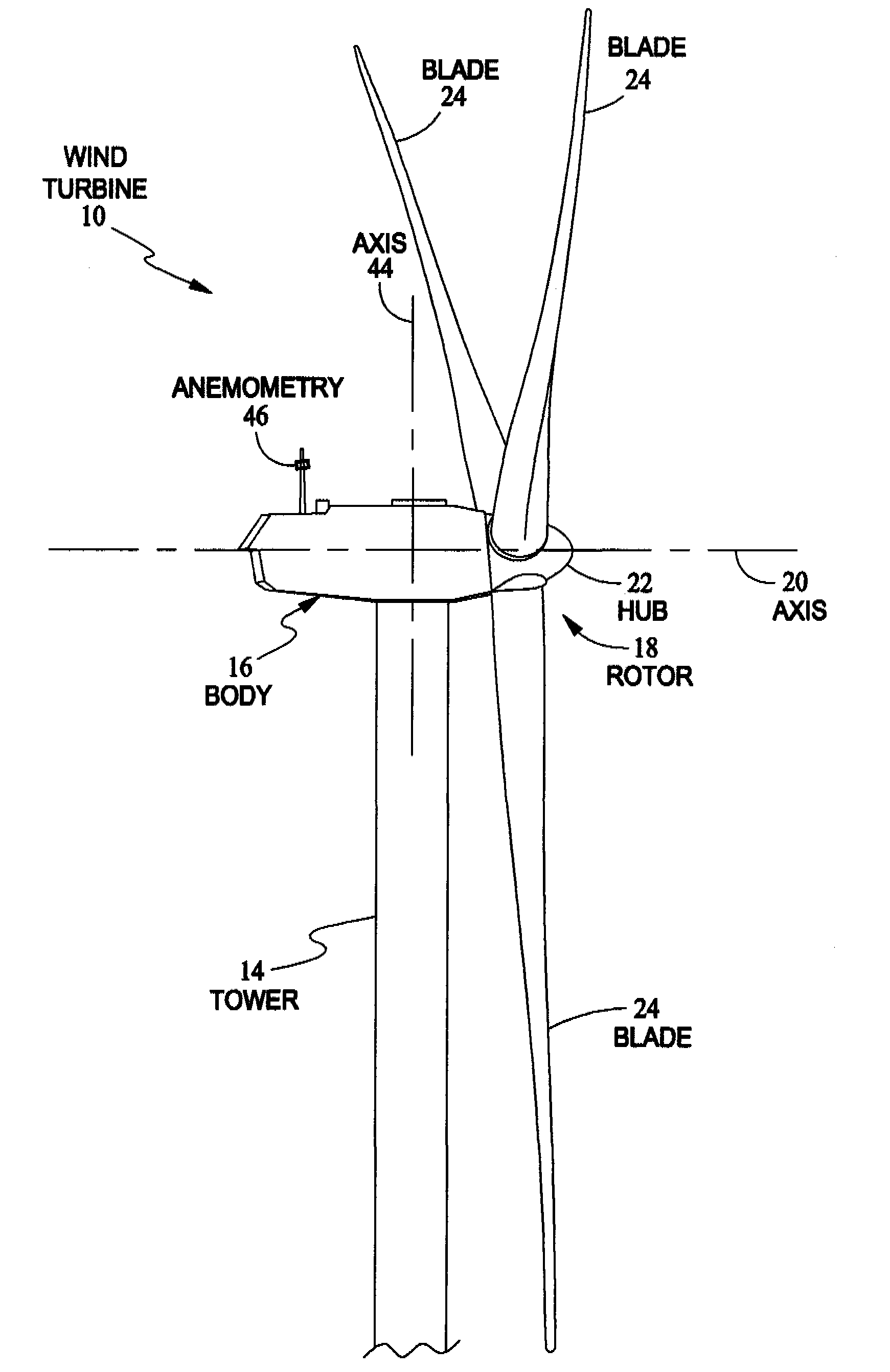
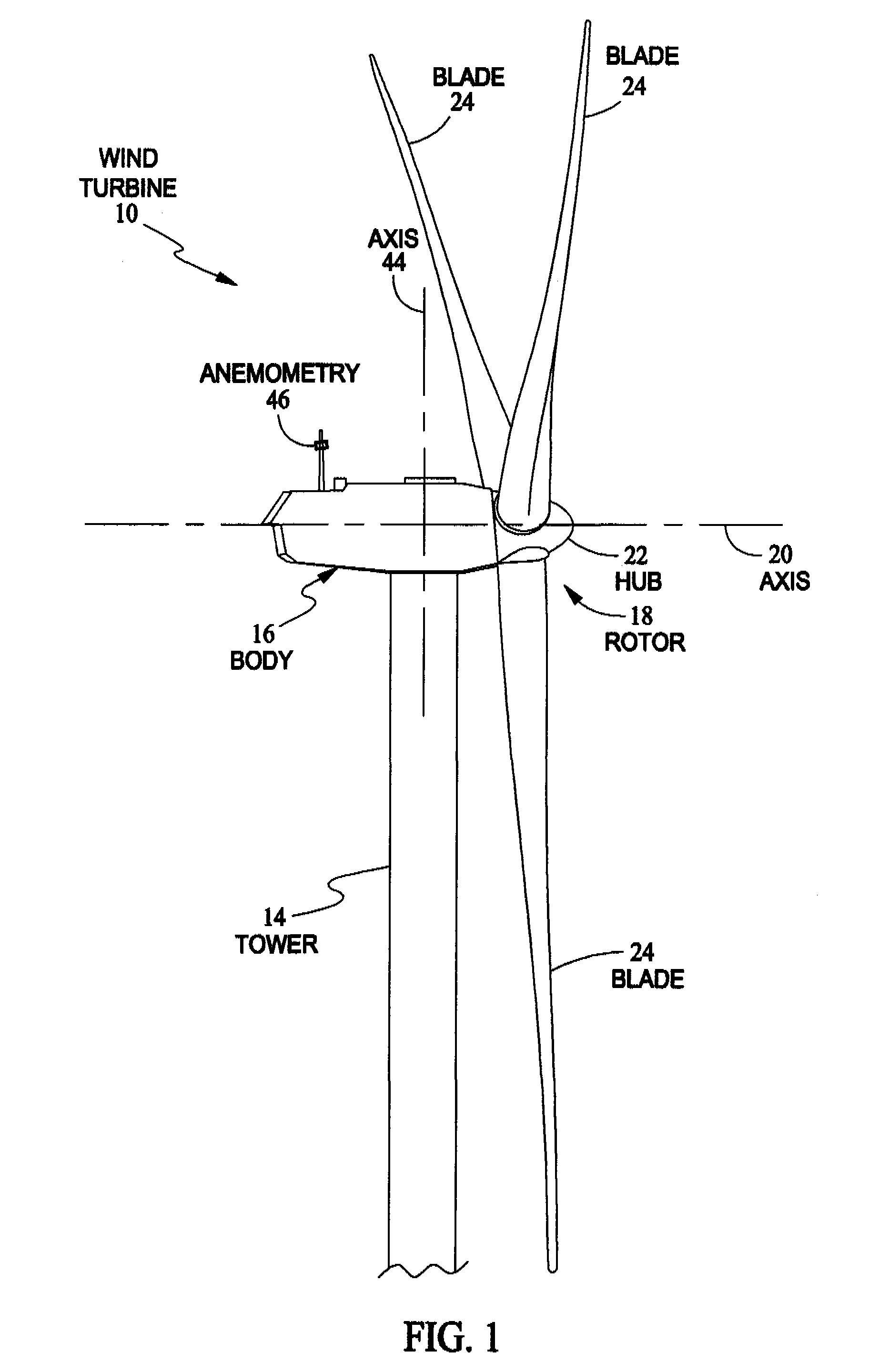
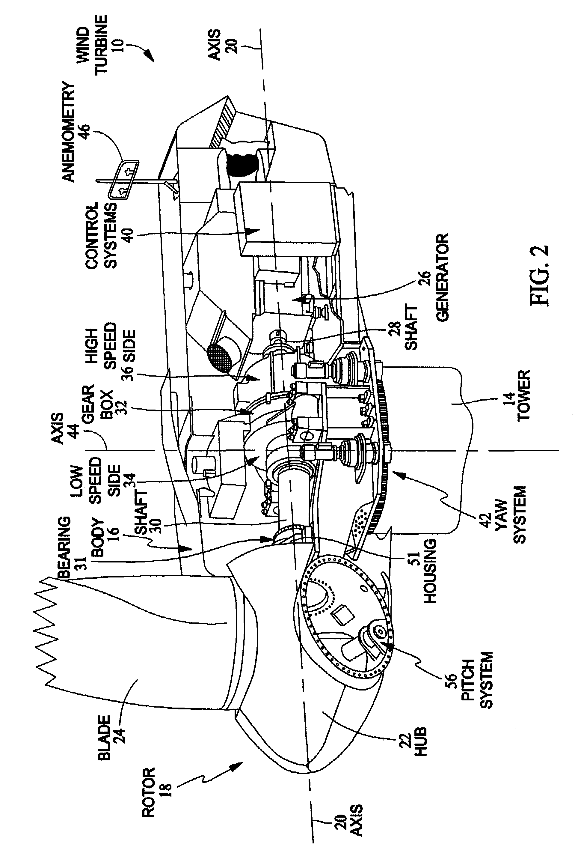
[0009]As used herein, the term “blade” is intended to be representative of any device that provides reactive force when in motion relative to a surrounding fluid. As used herein, the term “wind turbine” is intended to be representative of any device that generates rotational energy from wind energy, and more specifically, converts kinetic energy of wind into mechanical energy. As used herein, the term “wind generator” is intended to be representative of any wind turbine that generates electrical power from rotational energy generated from wind energy, and more specifically, converts mechanical energy converted from kinetic energy of wind to electrical power. As used herein, the term “windmill” is intended to be representative of any wind turbine that uses rotational energy generated from wind energy, and more specifically mechanical energy converted from kinetic energy of wind, for a predetermined purpose other than generating electrical power, such as, but not limited to, pumping a...


PUM


Abstract

A method for balancing a rotor of a rotary machine, wherein the rotor includes at least two rotor blades and a rotor shaft, includes receiving at least one measurement of either a load, an acceleration, or a displacement that pertains to at least one bending moment acting on the rotor shaft, determining at least one value of the at least one bending moment acting on the rotor shaft based, at least in part, on the received at least one measurement, and determining a pitch offset angle value of at least one rotor blade that facilitates reducing the at least one bending moment acting on the rotor shaft.

Description

BACKGROUND OF THE INVENTION[0001]This invention relates generally to rotors, and more specifically to methods and apparatus for balancing a rotor.[0002]Utility grade wind turbines (i.e., wind turbines designed to provide electrical power to a utility grid) can sometimes have rotors of 30 or more meters in diameter. Imbalanced loading in the rotating frame acting on at least some known rotors may occur due to mass imbalance in the blade set, geometrical irregularities in rotor and / or blade mounting, differences in aerodynamic geometry (section, bend, and / or twist) between the blades, and / or differences in pitch angle zero point between the blades. Such imbalanced loads acting on the rotor may be induced to other components of the wind turbine, which may have an impact upon a number of fatigue cycles some components of the wind turbine experience. For example, unbalanced loads acting on the rotor may facilitate fatigue damage of a bedplate that connects a tower of the wind turbine to ...

Claims


Application Information

Patent Timeline
Patent Type & Authority Patents(United States)
IPC IPC(8): G01C17/00
CPCF03D1/008F03D7/0224F03D7/024F03D7/0296F03D7/042F05B2270/1095F05B2270/331Y02E10/721Y02E10/723F03D13/35Y02E10/72
Inventor PIERCE, KIRK GEESLACK, ROBERT PETER
Owner GENERAL ELECTRIC CO
Learn More