Method of discharging high pressure storage vessels

a storage tank and high-pressure technology, applied in the direction of water supply installation, container discharging methods, electrochemical generators, etc., can solve the problem of automatic closing of the valve, and achieve the effect of minimal electrical energy

Inactive Publication Date: 2008-09-23
GM GLOBAL TECH OPERATIONS LLC
View PDF5 Cites 18 Cited by
  • Summary
  • Abstract
  • Description
  • Claims
  • Application Information

AI Technical Summary

Benefits of technology

[0013]In accordance with the teachings of the present invention, a master / slave tank system for storing a compressed gas, such as hydrogen, is disclosed that employs an automatic shut-off valve for each tank in the system. The tank system includes a master tank and at least one slave tank for storing the gas. A first line is coupled to the master tank for providing the gas stored therein to a gas using device, such as a fuel cell stack. At least one pressure regulator is provided in the first line between the master tank and the gas-using device. A master tank shut-off valve is positioned in the first line between the master tank and the pressure, regulator, where the master tank shut-off valve automatically closes the first line in response to a gas leak in the first line, or closes the first line during normal operating conditions, such as system shut-down. A second line is coupled to the slave tank for providing the gas stored therein to refuel the master tank as the pressure difference between the slave tank and the master tank changes when the gas is output from the master tank on the first line. A slave tank shut-off valve is positioned within the second line, where the slave tank shut-off valve automatically closes the second line in response to a gas leak in the second line, or closes the second line during normal operating conditions. Because the differential pressure across the slave tank shut-off valve is low, minimal electrical energy is required to maintain the valve in the open position, and a relatively small increase in the differential pressure across the slave tank shut-off valve, as a result of a line rupture or leak, will cause the valve to automatically close.

Problems solved by technology

Because the differential pressure across the slave tank shut-off valve is low, minimal electrical energy is required to maintain the valve in the open position, and a relatively small increase in the differential pressure across the slave tank shut-off valve, as a result of a line rupture or leak, will cause the valve to automatically close.

Method used


Image

  • Method of discharging high pressure storage vessels
  • Method of discharging high pressure storage vessels
  • Method of discharging high pressure storage vessels

Examples


Embodiment Construction

[0018]The following discussion of the embodiments of the invention directed to a master / slave tank system for storing a compressed gas is merely exemplary in nature, and is in no way intended to limit the invention or its applications or uses. Particularly, the discussion herein describes the tank system for storing compressed hydrogen gas for a fuel cell system on a vehicle. However, the tank system of the invention has other applications for storing other gases for other systems, including natural gas.

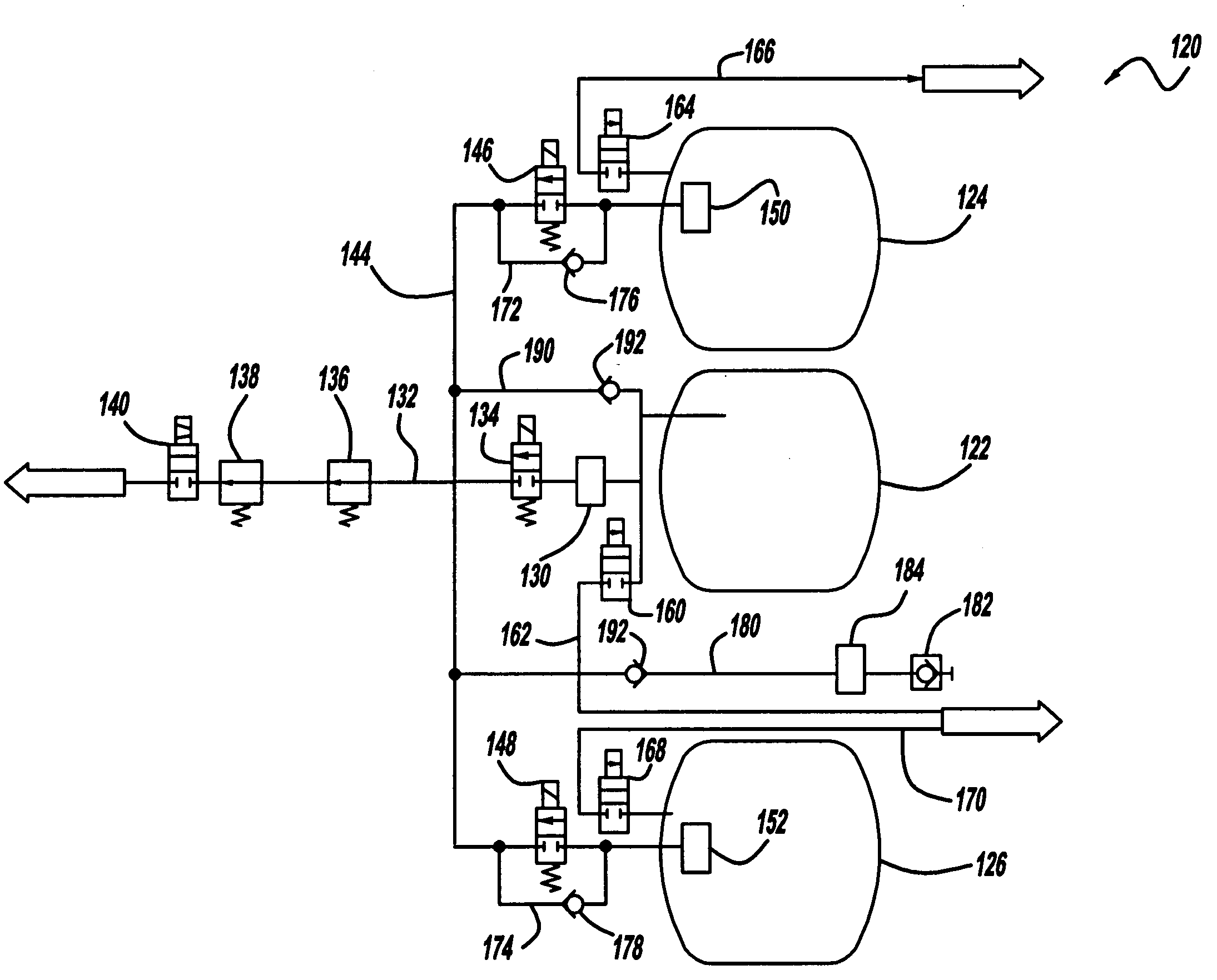
[0019]FIG. 3 is a schematic plan view of a master / slave tank system 120 including a master tank 122, a first slave tank 124 and a second slave tank 126, according to an embodiment of the present invention. The tank system 120 is similar to the tank system 10 in that the hydrogen gas for a fuel cell stack (not shown) is provided from the master tank 122, and the slave tanks 124 and 126 feed the master tank 122 to stabilize the pressure in all three of the tanks 122-126. The hydrogen g...


PUM


Abstract

A master / slave tank system for storing a compressed hydrogen gas, where the system employs an electrically driven shut-off valve for each tank in the system. The tank system includes a master tank and a slave tank for storing the gas. A first line is coupled to the master tank for providing the gas stored therein to a fuel cell stack. A master tank shut-off valve is positioned in the first line between the master tank and a pressure regulator. A second line is coupled to the slave tank for providing the gas stored therein to the master tank as the pressure difference between the slave tank and the master tank changes. An electrically driven slave tank shut-off valve is positioned within the second line, where the slave tank shut-off valve automatically closes the second line in response to an increase in the differential pressure across the slave tank valve.

Description

BACKGROUND OF THE INVENTION[0001]1. Field of the Invention[0002]This invention relates generally to a storage tank system for storing a high pressure gas and, more particularly, to a storage tank system for storing a high pressure gas, where the tank system includes a master tank having a master tank shut-off valve and at least one slave tank having a slave tank shut-off valve, and where the slave tank shut-off valve has a low pressure differential so that a rupture or leak will cause it to automatically close.[0003]2. Discussion of the Related Art[0004]Hydrogen is a very attractive fuel because it is clean and can be used to efficiently produce electricity in a fuel cell. The automotive industry expends significant resources in the development of hydrogen fuel cells as a source of power for vehicles. Such vehicles would be more efficient and generate fewer emissions than today's vehicles employing internal combustion engines. In an automotive fuel cell application, the hydrogen fue...

Claims


Application Information

Patent Timeline
Patent Type & Authority Patents(United States)
IPC IPC(8): F17C13/04F17C7/00
CPCF17C7/00F17C13/026F17C13/025Y02E60/321F17C2205/0138F17C2205/0142F17C2205/0323F17C2205/0341F17C2205/0391F17C2221/012F17C2223/0123F17C2223/036F17C2225/0123F17C2225/036F17C2227/0107F17C2227/0192F17C2250/01F17C2250/043F17C2250/0439F17C2250/0447F17C2265/012F17C2270/0139F17C2270/0184Y10T137/87507Y10T137/86196Y10T137/4857Y10T137/87555Y10T137/4673Y10T137/4807Y02E60/32
Inventor SCHWAN, MIRKOWINKELMANN, HOLGEROELERICH, WOLFGANG
Owner GM GLOBAL TECH OPERATIONS LLC
Why Eureka
Try Eureka