Irrigation control valve and system

a technology of irrigation control valve and control valve, which is applied in the direction of automatic control, process and machine control, instruments, etc., can solve the problems of network nodes' cost and communication energy requirements

Active Publication Date: 2007-12-06
DEERE & CO
View PDF17 Cites 6 Cited by
  • Summary
  • Abstract
  • Description
  • Claims
  • Application Information

AI Technical Summary

Benefits of technology

[0008]It is an advantage of the invention that the electronically controlled member and the electronically controlled actuator need only to move when a desired level of moisture in the soil changes. Since this usually takes place over longer intervals, minimal electric energy for moving the electronically controlled member is required. Changes in the actual moisture content of the soil occurring with higher frequency, dependent on the daytime evaporation, etc., only influence the moisture controlled member which does not require electric energy.
[0009]The electronic controller can be controlled from a remote station at which a computer is located. A user can input data containing information about the desired amount of moisture in the ground into the computer, which data are sent to the electronic controller wirelessly by radio frequency transmission or via a wired control network. The information about the desired amount of moisture in the ground can alternatively or additionally be provided by a control program running on the computer and / or on the controller of the irrigation valve, the program using a model based upon plant characteristics and environmental information.

Problems solved by technology

One of the challenges to this approach is the cost of the network nodes and the energy they require for communication, especially for powering electro-mechanical actuators such as irrigation valves.

Method used


Image

  • Irrigation control valve and system
  • Irrigation control valve and system
  • Irrigation control valve and system

Examples


Embodiment Construction

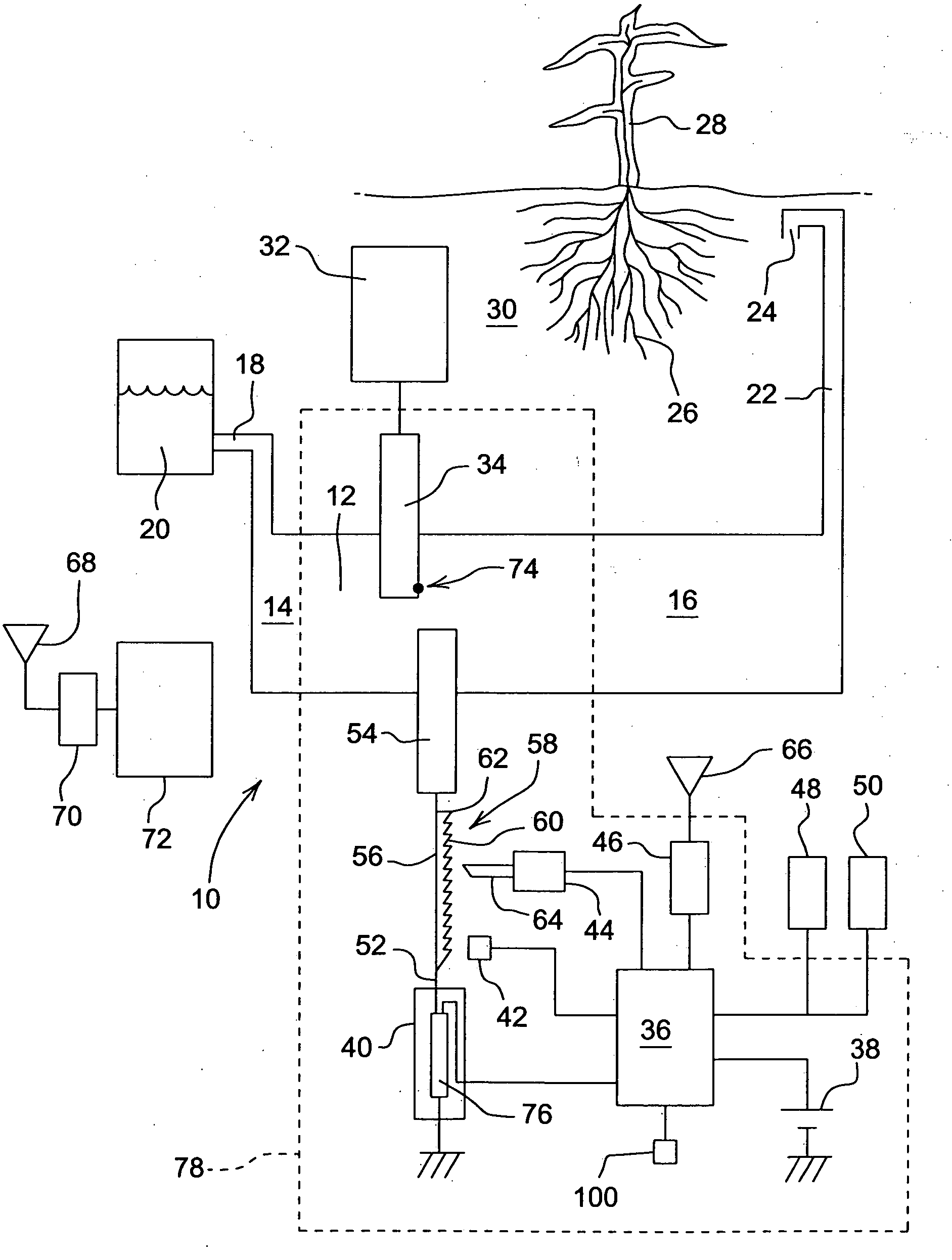
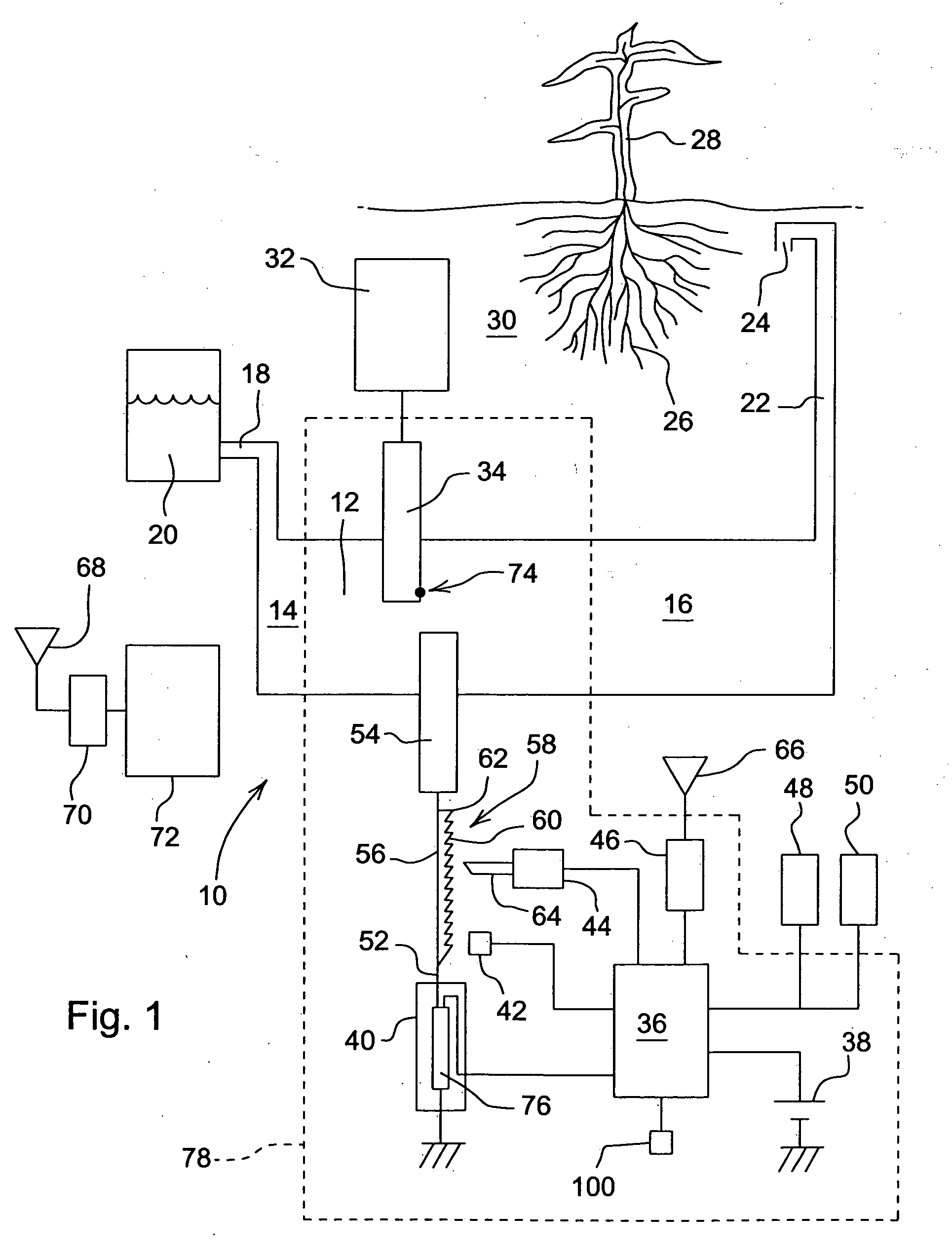
[0019]In FIG. 1, an irrigation control system according to the invention is shown in a schematic manner. The irrigation control system utilizes an irrigation control valve 10 comprising a conduit 12 having an inlet 14 and an outlet 16. The cross section of conduit 12 can be circular or rectangular or of any other suitable shape. Inlet 14 is connected via an inlet pipe 18 to a supply 20 of water. The supply 20 can be any suited source of water, especially a tank or cistern standing upon the ground or buried therein collecting rainwater or any other water, a lake, a spring or a water-conducting layer in the ground. A pump (not shown) can be provided between the supply 20 and the inlet 14, if required. The outlet 16 is connected by means of an outlet pipe 22 to a water discharge 24 located in the vicinity of roots 26 of a plant 28, for example a vine plant. The roots 26 are within soil 30 surrounding them.

[0020]The irrigation control valve 10 comprises a moisture sensitive element 32 l...


PUM


Abstract

An irrigation control valve has two movable members that can independently or in combination block the flow of water in a conduit, or be fully retracted of at some point in-between. A moisture sensitive element is arranged to be placed in contact with the soil and expands or retracts dependent on the moisture within soil adjacent the moisture sensitive element. The moisture sensitive element is connected or coupled to a moisture controlled member. Dependent on the moisture of the soil adjacent the moisture sensitive element, the moisture controlled member is moved further into the conduit with increasing moisture in the soil. The moisture controlled member and an electronically controlled member are located adjacent each other at the conduit. The electronically controlled member determines how far the moisture controlled member needs to move in order to fully block the flow of water in the conduit. An electronic controller is operable to determine the achieved level of moisture in the soil, by means of the electronically controlled actuator and the electronically controlled member.

Description

FIELD OF THE INVENTION[0001]The present invention relates to agricultural and landscape irrigation, and more specifically, an irrigation control valve and system for irrigating plants.BACKGROUND OF THE INVENTION[0002]Increasing scarcity and cost of water is driving advances in irrigation. In California and Australia, for example, wine growers are now utilizing techniques such as root deficit irrigation (RDI) and partial root zone drying (PRD). The grapevines are hence irrigated with less water than in conventional viniculture. These techniques not only save water, but can increase the value of the crop by improving crop attributes for which the market will pay a premium. These techniques will reach maximum effectiveness when irrigation can be economically controlled on a plant-by-plant basis.[0003]Another advance in irrigation is the deployment of wireless sensor networks to enhance crop management. One of the challenges to this approach is the cost of the network nodes and the ener...

Claims


Application Information

Patent Timeline
Patent Type & Authority Applications(United States)
IPC IPC(8): F16K17/36
CPCA01G25/16Y10T137/88062Y10T137/189Y10T137/88022
Inventor ANDERSON, NOEL W.STELFORD, MARK W.
Owner DEERE & CO
Why Eureka
Try Eureka