
Apparatus, system, and method for bus link width optimization of a graphics system

a graphics system and bus link technology, applied in the field of apparatus, system and method for bus link width optimization of a graphics system, can solve problems such as achieve the effects of reducing bus power requirements, reducing bandwidth requirements, and high bandwidth

Inactive Publication Date: 2008-09-16
NVIDIA CORP
View PDF12 Cites 106 Cited by
  • Summary
  • Abstract
  • Description
  • Claims
  • Application Information

AI Technical Summary

Benefits of technology

[0007]An apparatus, system, and method is disclosed in which a data bus has a plurality of operable data lanes that may be associated to form a data link between components. The data bus permits the number of active data lanes of the data link to be adaptively adjusted in response to changes in bus bandwidth requirements. The bus is configured to have a sufficient number of active lanes to provide a high bandwidth for operational states requiring high bandwidth. However, for operational states requiring less bandwidth, the bus is configured to have a smaller number of active lanes sufficient to supply the reduced bandwidth requirement of the operational state, reducing the bus power requirements.

Problems solved by technology

However, for operational states requiring less bandwidth, the bus is configured to have a smaller number of active lanes sufficient to supply the reduced bandwidth requirement of the operational state, reducing the bus power requirements.

Method used


Image

  • Apparatus, system, and method for bus link width optimization of a graphics system
  • Apparatus, system, and method for bus link width optimization of a graphics system
  • Apparatus, system, and method for bus link width optimization of a graphics system

Examples


Embodiment Construction

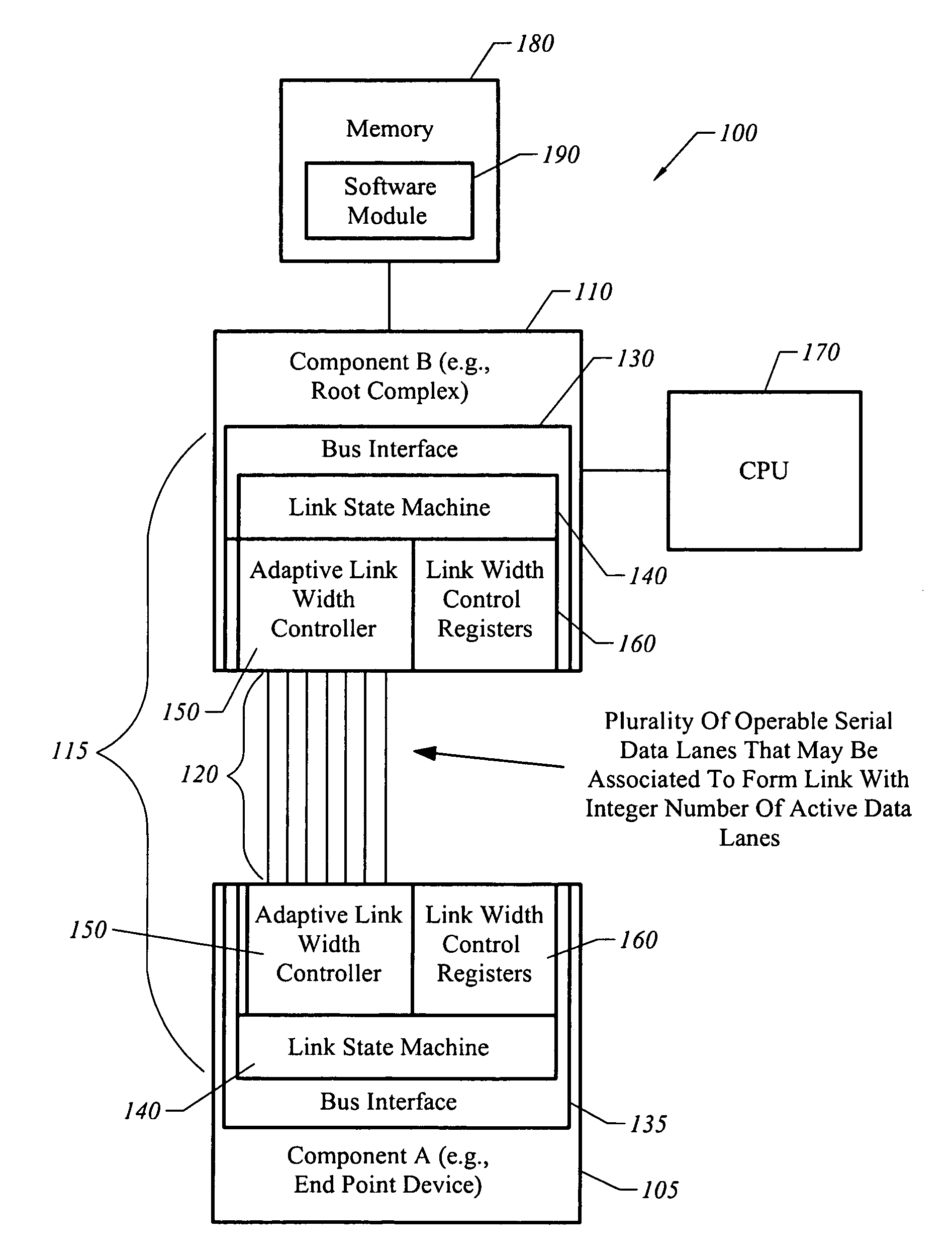
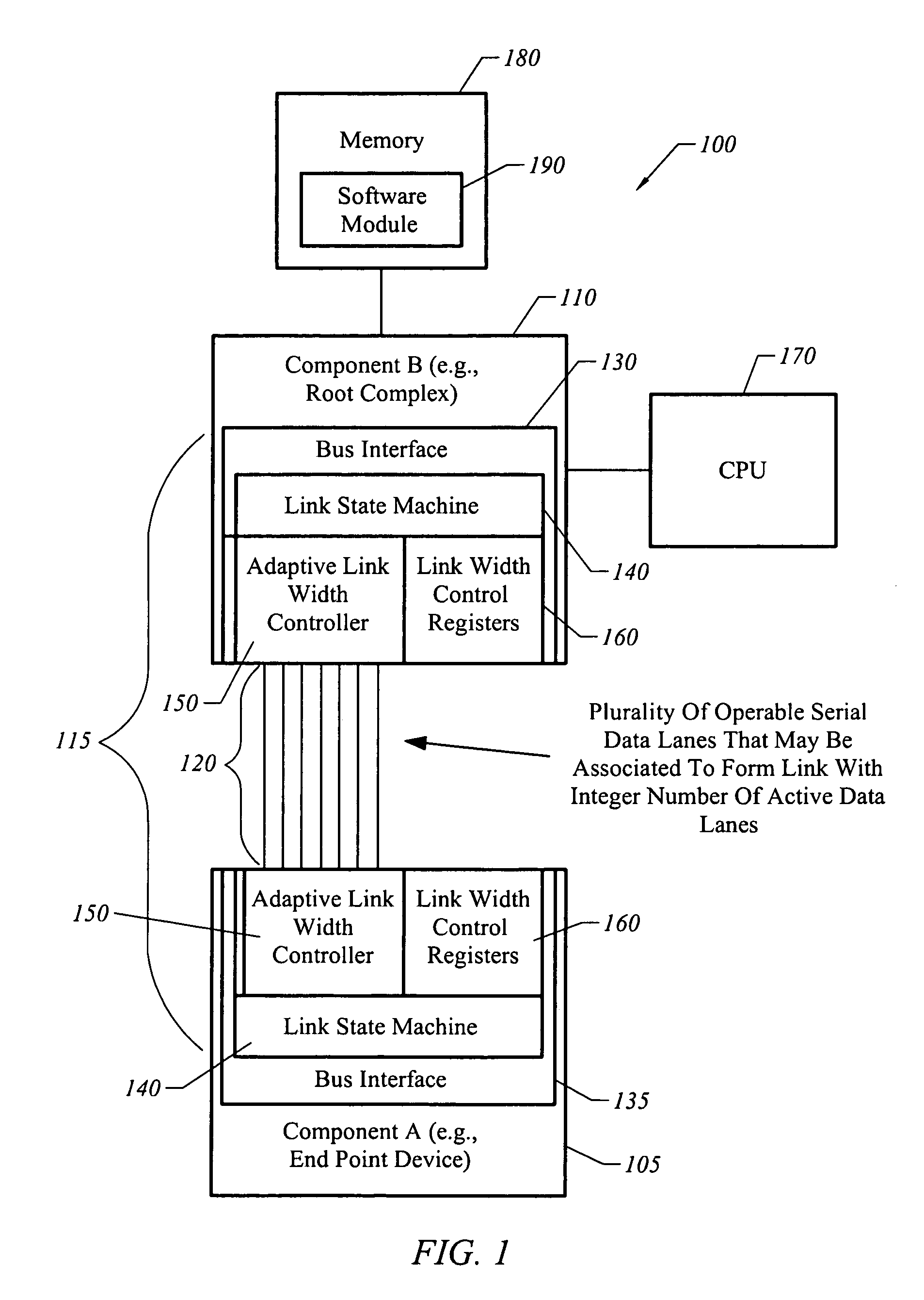
[0030]The present invention is directed towards an apparatus, system, and method for adaptively adjusting bus bandwidth. FIG. 1 is an illustrative block diagram of a system 100 in accordance with one embodiment of the present invention. Referring to FIG. 1, system 100 includes two components 105 and 110 that are communicatively coupled by a data bus 115 comprised of a plurality of serial data lanes 120 and bus interfaces 130 and 135.

[0031]In some embodiments, bus 115 is part of a system in which a first component 105 is an end-point device, such as a graphical processing unit (GPU). The other component 110 may correspond to a bridge, such as a root complex for peripheral devices. A CPU 170 and memory 180 having executable software instructions 190 may be coupled to component 110. However, it will be understood in the following description that bus 115 may be utilized in a variety of systems other than that illustrated in FIG. 1.

[0032]In one embodiment, each of the serial data lanes ...


PUM


Abstract

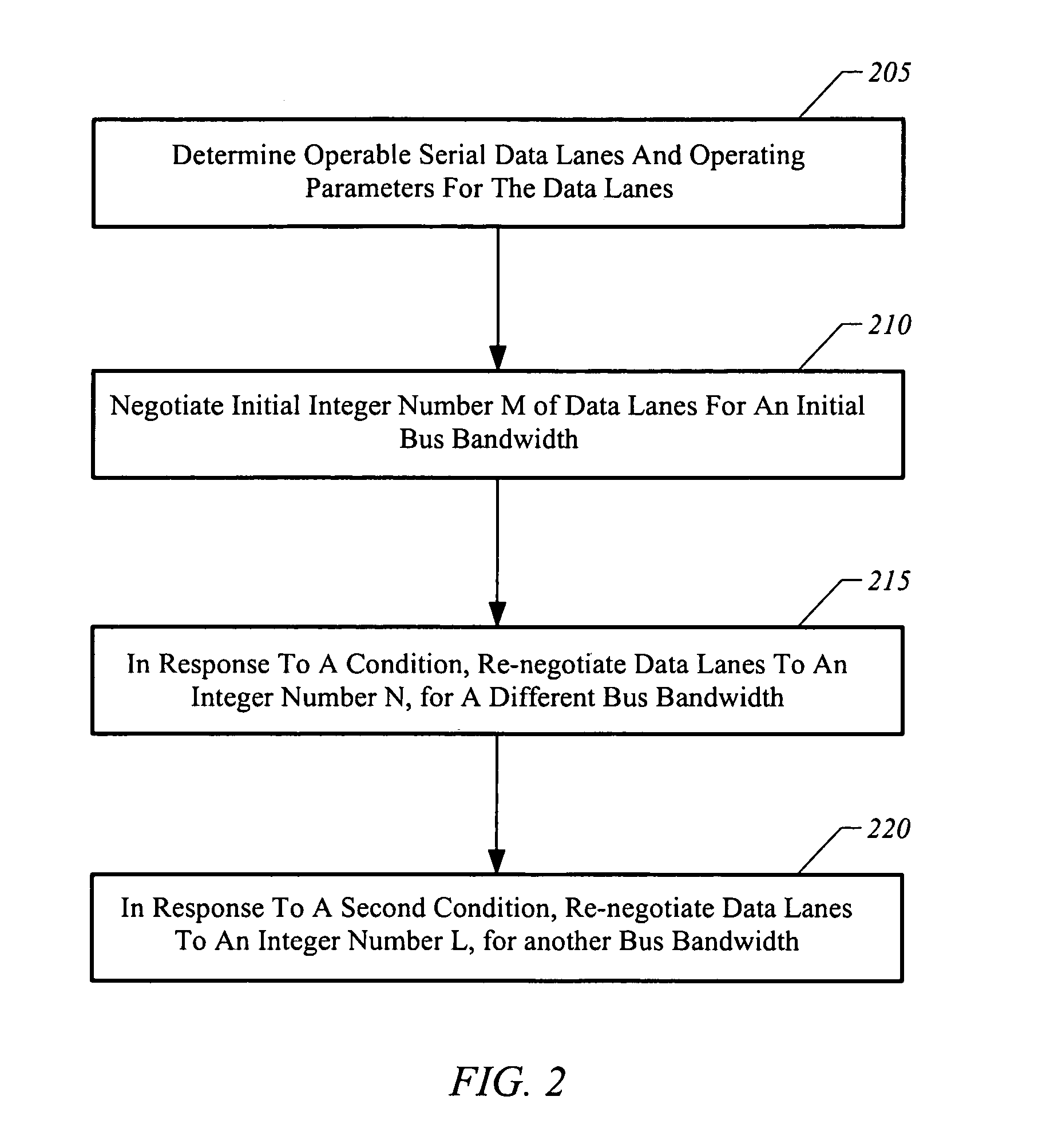
A bus permits the number of active serial data lanes of a data link to be re-negotiated in response to changes in bus bandwidth requirements. In one embodiment, one of the bus interfaces triggers a re-negotiation of link width and places a constraint on link width during the re-negotiation.

Description

CROSS REFERENCE TO RELATED APPLICATIONS[0001]This application is a continuation-in-part of U.S. patent Ser. No. 10 / 431,994 filed on May 7, 2003 now U.S. Pat. No. 7,136,953, the contents of which are hereby incorporated by reference.BRIEF DESCRIPTION OF THE INVENTION[0002]The present invention is generally related to bus power optimization for a bus comprised of a plurality of serial data lanes. More particularly, the present invention is directed towards optimizing bus power in peripheral component interfaces.BACKGROUND OF THE INVENTION[0003]There is an increasing need to reduce the power consumption of personal computers and other types of computing devices. A high-power consumption is undesirable because it increases the cooling requirements of the personal computer. Additionally, a high-power consumption is undesirable because it reduces the battery lifetime of mobile computers.[0004]There are several components of a personal computer that draw significant amounts of power. First...

Claims


Application Information

Patent Timeline
Patent Type & Authority Patents(United States)
IPC IPC(8): G06F13/40
CPCG06F13/4018Y02B60/1235Y02B60/1228Y02D10/00
Inventor TSU, WILLIAM P.BISSON, LUC R.RUBINSTEIN, ORENHUANG, WEI-JEDIAMOND, MICHAEL B.
Owner NVIDIA CORP
Learn More