
Compact, high power, fiber pigtailed faraday isolators

a faraday isolator, fiber pigtail technology, applied in the direction of optics, polarising elements, instruments, etc., can solve the problems of high average power, erratically operated, lasers used in industrial metalworking applications are particularly prone to metal workpiece reflection, etc., to achieve low cost and high average power

Active Publication Date: 2008-09-16
ELECTRO OPTICS TECH
View PDF12 Cites 18 Cited by
  • Summary
  • Abstract
  • Description
  • Claims
  • Application Information

AI Technical Summary

Benefits of technology

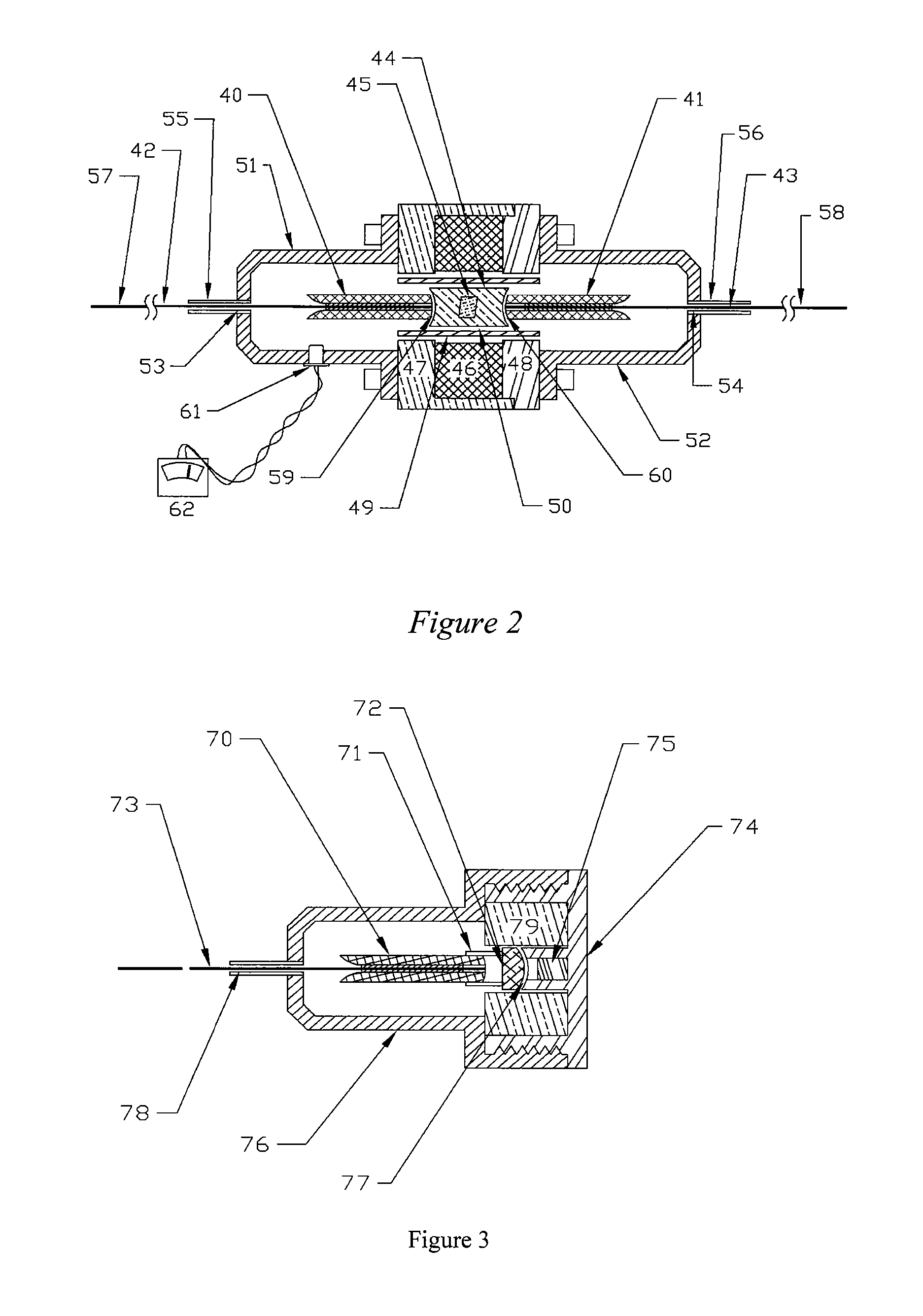
[0018]An advantage of the invention is the realization of compact Polarization Maintaining Faraday isolators that are also low cost and robust. In addition to stripping any cladding modes due to thermal effects, the mode stripping elements, namely ferrules / collimators, strip the polarization scattered into the cladding by the single polarization fiber. The length of the mode stripping ferrule is chosen such that the rejected polarization power is safely below the threshold for material damage in the fiber polymer protective coating.
[0019]Beyond the examples of a mode stripping ferrules described herein, there are other suitable ferrule designs, as for example described in U.S. patent application Ser. No. 11 / 338,429 filed Jan. 23, 2006, entitled Monolithic Mode Stripping Ferrule, and assigned to the same assignee as the present application. The content of that disclosure is incorporated herein by reference for all purposes.
[0020]A further aspect of the present invention is the arrangement by proper tilting of the surfaces of the birefringent wedges relative to the Faraday optic such that the original beam path and the initial beam parameters of a laser beam are restored so it is along a reasonably straight and narrow path through a passage in the magnet package, after the beam has propagated through the wedges, Faraday optic and a final beam displacer. This aspect of the invention allows the magnet package to be compact so as to be consistent with the compact optical structure enabled by mode stripping collimators.
[0021]One advantage of the present invention is that use of a mode stripping ferrule / collimator on the output of a Faraday isolator enables consistent output beam focusing properties at high average power. The focusing beam parameters of the beam exiting the output fiber are dictated by the wave-guiding properties of the fiber itself, independent of changes in average laser power or any variable thermal lensing present in the optical elements within the Faraday isolator.
[0022]In an embodiment of the invention, at least one detector or thermal sensor is mounted in the collimator fiber strain relief cover to quantitatively monitor the magnitude of radiation scattered from the mode stripping collimators, if desired. Such monitoring could be used, for example, to quantify backward propagating radiation that is scattered by the input collimator for various system feedback purposes.
[0023]The invention is not limited to fiber pigtailed Faraday isolators. Other fiber pigtailed Faraday devices, such as circulators, rotators and Faraday mirrors suitable for high power applications, are contemplated by the invention.

Problems solved by technology

Reflections can damage the laser and / or cause it to operate erratically.
Lasers used in industrial metalworking applications are particularly prone to reflections from metal work-pieces.
With high power lasers however, the optical radiation (e.g., IR light) which does not couple into the core of the output collimator either couples into the surrounding cladding layer, from which it ultimately diverges and readily burns the optical fiber polymer protective coating layer, thereby destroying the fiber, or it destroys the fiber collimator if it strikes any adhesives which hold the fiber in alignment.
This is a practical problem for fiber pigtailed high power Faraday isolators because Faraday isolators are used at wavelengths near an absorption peak where there is always a residual absorption.
Increasing the beam size through the Faraday optic can reduce this thermal lensing, but it does so at the expense of making the device bulkier.
These changed polarization states will also not couple efficiently into the core of a second (output) fiber collimator.
However, these types of polarizers function by absorbing or scattering the undesired polarization component.
Thus, they are readily prone to failure if the same designs are employed for high power applications.
A disadvantage of this approach is that the effective aperture size of the Faraday isolator is typically doubled in order to transmit both orthogonally polarized beams.
The result is that an already bulky magnetic encasement must be even larger.
For high power laser application where it is desired to increase the laser beam size to reduce thermal lensing, the indicated size of such beam displacers is very large and difficult to fabricate with high optical quality.
Even so, such bulky designs have found wide usage in industrial settings with fiber pigtailing because any reflected power back into the isolator is blocked by physical beam blocks rather than being coupled back into the input fiber collimator where damage could occur.
TGG is a much less efficient Faraday optic material than BIG, which cannot be used at such wavelengths due to a strong absorption.
This significantly increases the size of the overall package.
This diminishes the potential size and cost benefits which birefringent wedge based PI isolator designs have over a bulky beam displacer based approach.
However at average power levels as low as 10 W, such isolated power can damage the protective polymer coating of the input fiber.
Thus, fiber pigtailed birefringent wedge based PI isolators have not been considered suitable for high-power applications.

Method used


Image

  • Compact, high power, fiber pigtailed faraday isolators
  • Compact, high power, fiber pigtailed faraday isolators
  • Compact, high power, fiber pigtailed faraday isolators

Examples


Embodiment Construction

[0028]Reference is now made in detail to specific embodiments representative of the present invention to illustrate the practice of the invention as contemplated by the inventors. Additional features are described in connection with each embodiment. Alternate embodiments will be apparent to those of ordinary skill in the art in light of these descriptions.

[0029]FIG. 1 is a side cross-sectional view of a Polarization Independent Faraday isolator module according to the invention, wherein monolithic fused silica mode stripping ferrules 10 and 15 are employed. Suitable examples of such ferrules 10 and 15 are described in the disclosure of the above referenced commonly-owned patent application incorporated herein by reference. Input silica fiber 31, monolithic ferrule 10, fused silica sleeve 11 and silica aspheric lens 12 together form a substantially stable and compact mode stripping input fiber collimator assembly. Similarly, an output pigtailed collimator assembly is formed by fiber ...


PUM


Abstract

Faraday rotator or isolator with mode stripping ferrules and collimators having fiber pigtailed mode stripping components. An example is a compact Faraday Isolator module employing mode stripping ferrules and mode stripping collimators at the input and / or at the output of a fiber pigtailed Faraday Isolator. Two basic isolator types are a Polarization Independent Faraday isolator and a Polarization Maintaining Faraday isolator. The device is substantially immune to damage due to back-reflection, thermal lensing, energy leakage and absorption. Mode stripped optical energy propagating in the reverse direction is diverted onto a heat absorbing and heat sinking structure, as for example at the input of a compact birefringent wedge-based PI isolator. Alternatively, the optical energy propagating in the reverse direction is angularly refracted away from the forward incident beam path and is coupled into the energy dispersive cladding of the input fiber or the ferrule itself.

Description

CROSS-REFERENCES TO RELATED APPLICATIONS[0001]Not ApplicableSTATEMENT AS TO RIGHTS TO INVENTIONS MADE UNDER FEDERALLY SPONSORED RESEARCH OR DEVELOPMENT[0002]Not ApplicableREFERENCE TO A “SEQUENCE LISTING,” A TABLE, OR A COMPUTER PROGRAM LISTING APPENDIX SUBMITTED ON A COMPACT DISK[0003]Not ApplicableBACKGROUND OF THE INVENTION[0004]This invention relates to Faraday rotators and particularly Faraday isolators for use with high power lasers. Faraday isolators capable of withstanding high power are required to decouple high power laser sources from reflective targets. Reflections can damage the laser and / or cause it to operate erratically. Lasers used in industrial metalworking applications are particularly prone to reflections from metal work-pieces. For example, metal targets can couple nearly 100% of the incident radiation back into industrial 1 μm laser sources.[0005]Optical fiber is particularly useful for delivering high power laser radiation in industrial environments. It is sea...

Claims


Application Information

Patent Timeline
Patent Type & Authority Patents(United States)
IPC IPC(8): G02B6/26
CPCG02F1/095G02B6/2746
Inventor SCERBAK, DAVID GERALDPOOLER, ERIC SEAN
Owner ELECTRO OPTICS TECH
Learn More