
Wireless optical input device

a wireless input and optical input technology, applied in instruments, sensing record carriers, computing, etc., can solve the problems of limiting the area on which the input device can move, debris and wear and tear, and easy malfunction of the actuating assembly (e.g., the roller ball and the corresponding roller), so as to avoid premature depletion and manage the power consumption of the wireless devi

Inactive Publication Date: 2008-09-16
PERSISTENCE SOFTWARE
View PDF17 Cites 14 Cited by
  • Summary
  • Abstract
  • Description
  • Claims
  • Application Information

AI Technical Summary

Benefits of technology

"The present invention provides a wireless input device that uses optical sensing for things like cursor movement and scrolling. The device has a power management algorithm to avoid premature depletion of its battery. The invention also provides a method for managing power consumption on wireless devices."

Problems solved by technology

One problem associated with this type of electromechanical arrangement is that the actuating assembly (e.g., roller ball and the corresponding rollers) is prone to malfunction because of debris and or mechanical breakdown.
This special surface is equally prone to debris and wear and tear, and tends to limit the area upon which the input device can move.
However, it appears that there is currently no computer input device that employs such optical sensing technology in the context of a wireless input device.
Problems associated with such a wireless optical input device stem from competing factors underlying the two technologies.
For instance, on one hand, optical assemblies require a significant amount of power (e.g., for powering the LED and optical sensor).
This basically limits the power source to a battery included in the wireless input device.
To complicate matters, both practical and economic reasons dictate that the battery size cannot exceed certain physical constraints thereby limiting the life of the battery.
As such, power intensive technology can prematurely deplete a battery included in a wireless input device.

Method used


Image

  • Wireless optical input device
  • Wireless optical input device
  • Wireless optical input device

Examples


Embodiment Construction

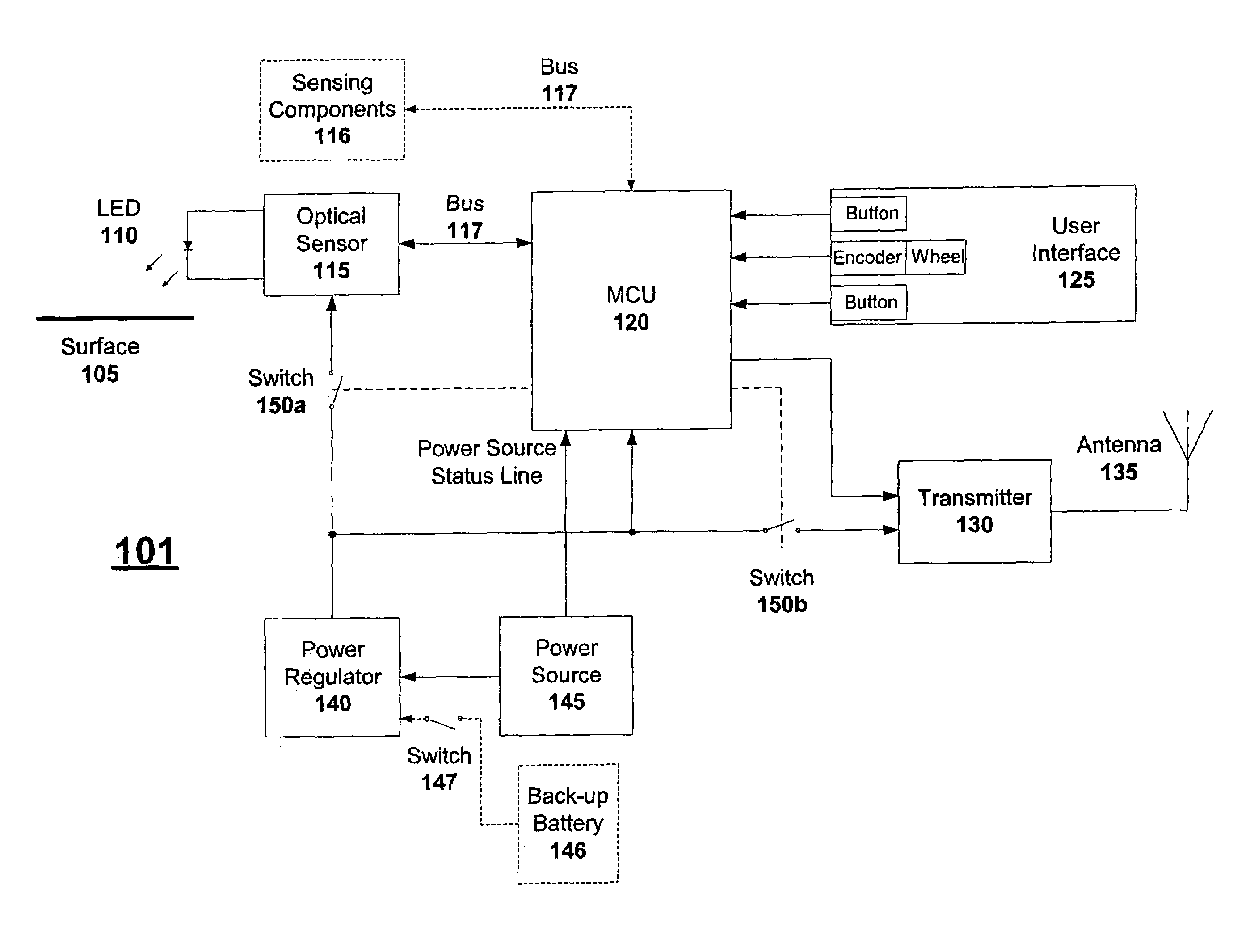
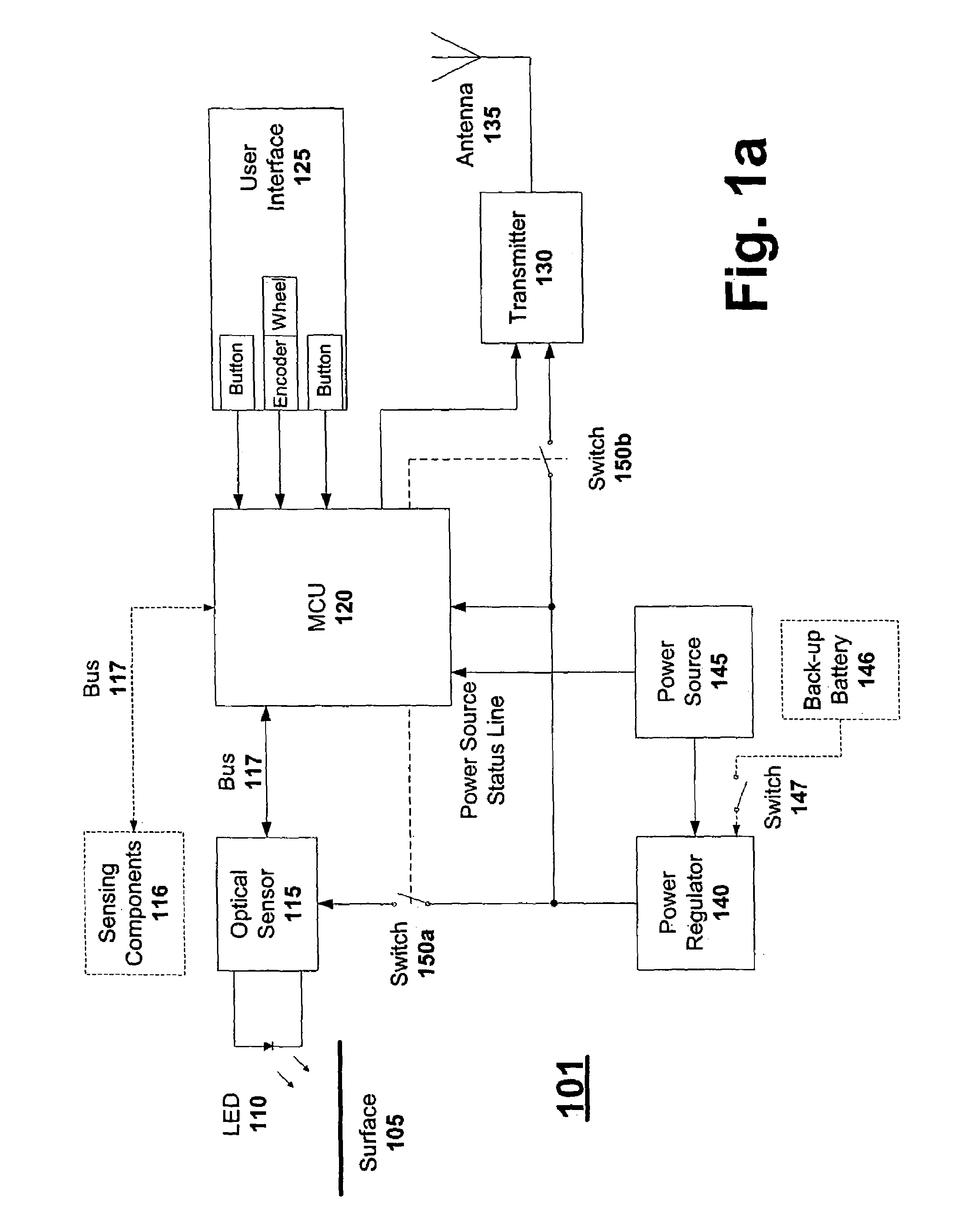
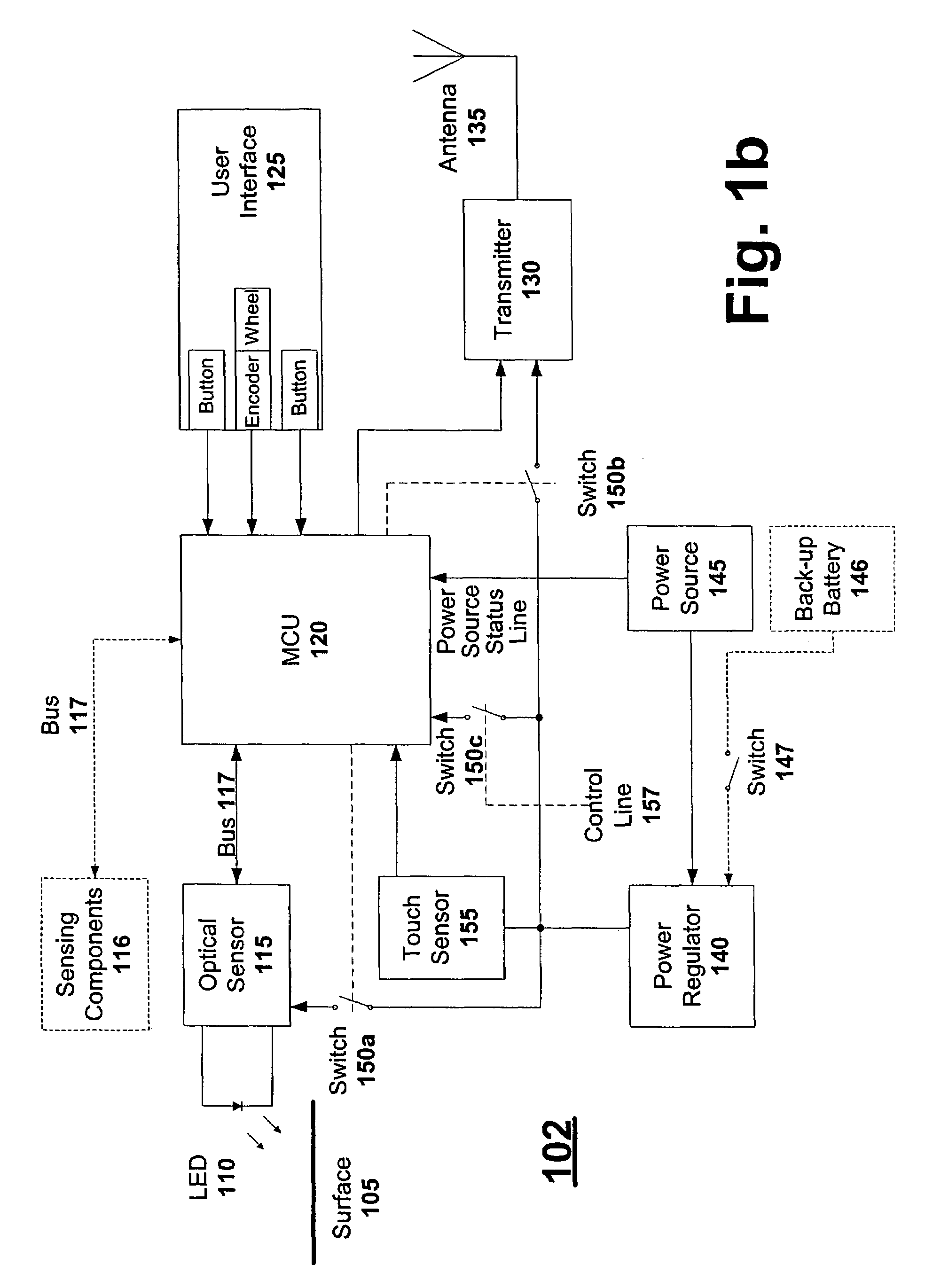
[0016]FIG. 1a illustrates a block diagram of a wireless input device that employs an optical sensor in accordance with one embodiment of the present invention. Device 101 includes a LED 110, an optical sensor 115, a microcontroller unit (MCU) 120, a user interface 125, a transmitter 130, an antenna 135, a power regulator 140, a power source 145 and switches 150a and 150b. One embodiment of optical sensor 115 includes a charged-coupled device (CCD) array and a lens for focusing reflected light onto the array. In alternative embodiments, optical sensor 115 can have a photo-sensitive element other than a CCD array, such as a number of photo-diodes or photo-transistors. In addition, optical sensor 115 might have no lens (e.g., reflected light is received directly by a photo-sensitive element) or more than one lens (e.g., one lens between LED 110 and surface 105, and a second lens between surface 105 and a photo-sensitive element of optical sensor 115). Likewise, LED 110 might have a len...


PUM


Abstract

One embodiment of the present invention provides a wireless input device that employs optical sensing to effect the likes of cursor movement and scrolling. Power management techniques can be optionally employed to avoid premature depletion of the wireless input device's power source. Another embodiment of the present invention provides a wireless device having a power management algorithm controlling its power consumption. Another embodiment of the present invention provides a method for managing the power consumption of a wireless device.

Description

CROSS-REFERENCE TO RELATED APPLICATIONS[0001]The present application is a continuation of U.S. patent application Ser. No. 09 / 709,046, filed Nov. 9, 2000, by Simone Arrigo, et al., now U.S. Pat. No. 6,781,570, issued Aug. 5, 2004, which subject matter is incorporated herein by this reference.FIELD OF THE INVENTION[0002]The invention relates to wireless devices, and more particularly, to a wireless optical input device that allows a user to interact with a computer.DESCRIPTION OF THE RELATED ART[0003]There are a number of computer input devices that employ an electromechanical arrangement for effecting cursor movement and scrolling. In such an arrangement, the mechanical movement of a roller ball is converted into electrical signals. The electrical signals are then encoded into information that a computer can use, such as cursor X-Y position data or scrolling direction and distance. Mice and trackballs are the most common input devices that employ this type of electromechanical arran...

Claims


Application Information

Patent Timeline
Patent Type & Authority Patents(United States)
IPC IPC(8): G09G5/08G06F3/03G06F3/033
CPCG06F3/0317
Inventor ARRIGO, SIMONEZAHND, DANIEL APIOT, JULIENKEHLSTADT, FLORIAN
Owner PERSISTENCE SOFTWARE
Learn More