
Electric hair-removing device

A technology for hair removal and equipment, applied in hairdressing equipment, scorching hair roots, hair or scalp washing devices, etc., can solve the problems of no switching path, operation switch cannot be operated, etc., to eliminate incorrect operation and avoid premature exhaustion , the effect of gentle closing

Active Publication Date: 2008-06-11
BRAUN AG
View PDF1 Cites 0 Cited by
  • Summary
  • Abstract
  • Description
  • Claims
  • Application Information

AI Technical Summary

Problems solved by technology

Apart from this swing position, there is no switching path available, and therefore the operating switch cannot be operated either

Method used


Image

  • Electric hair-removing device
  • Electric hair-removing device
  • Electric hair-removing device

Examples


Embodiment Construction

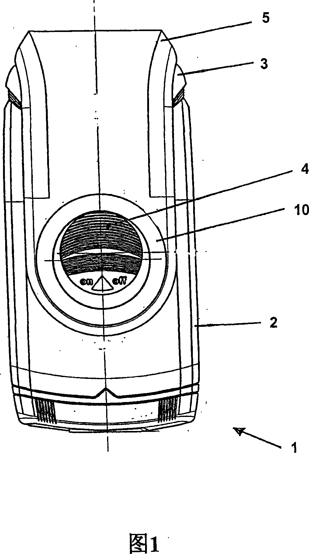
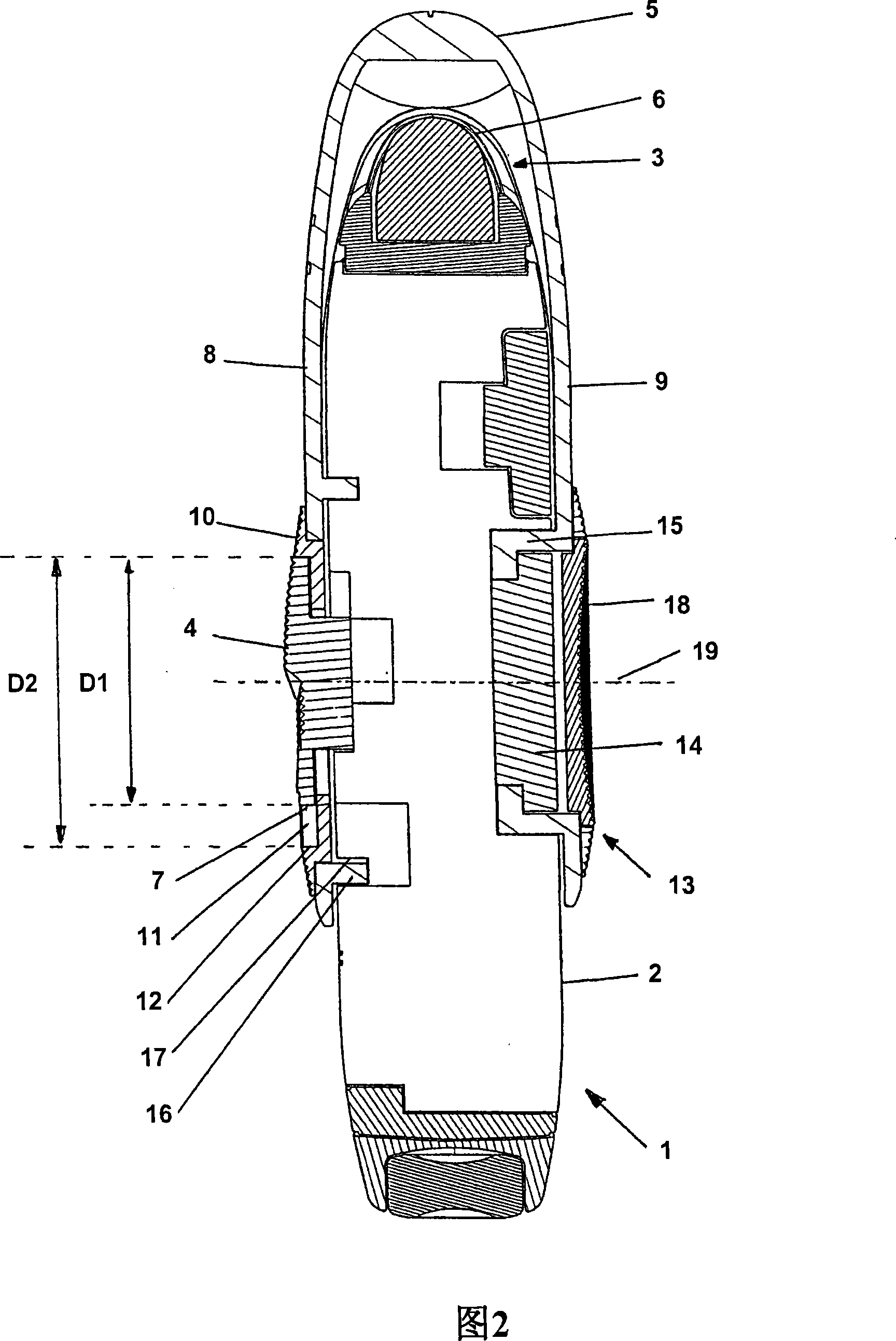
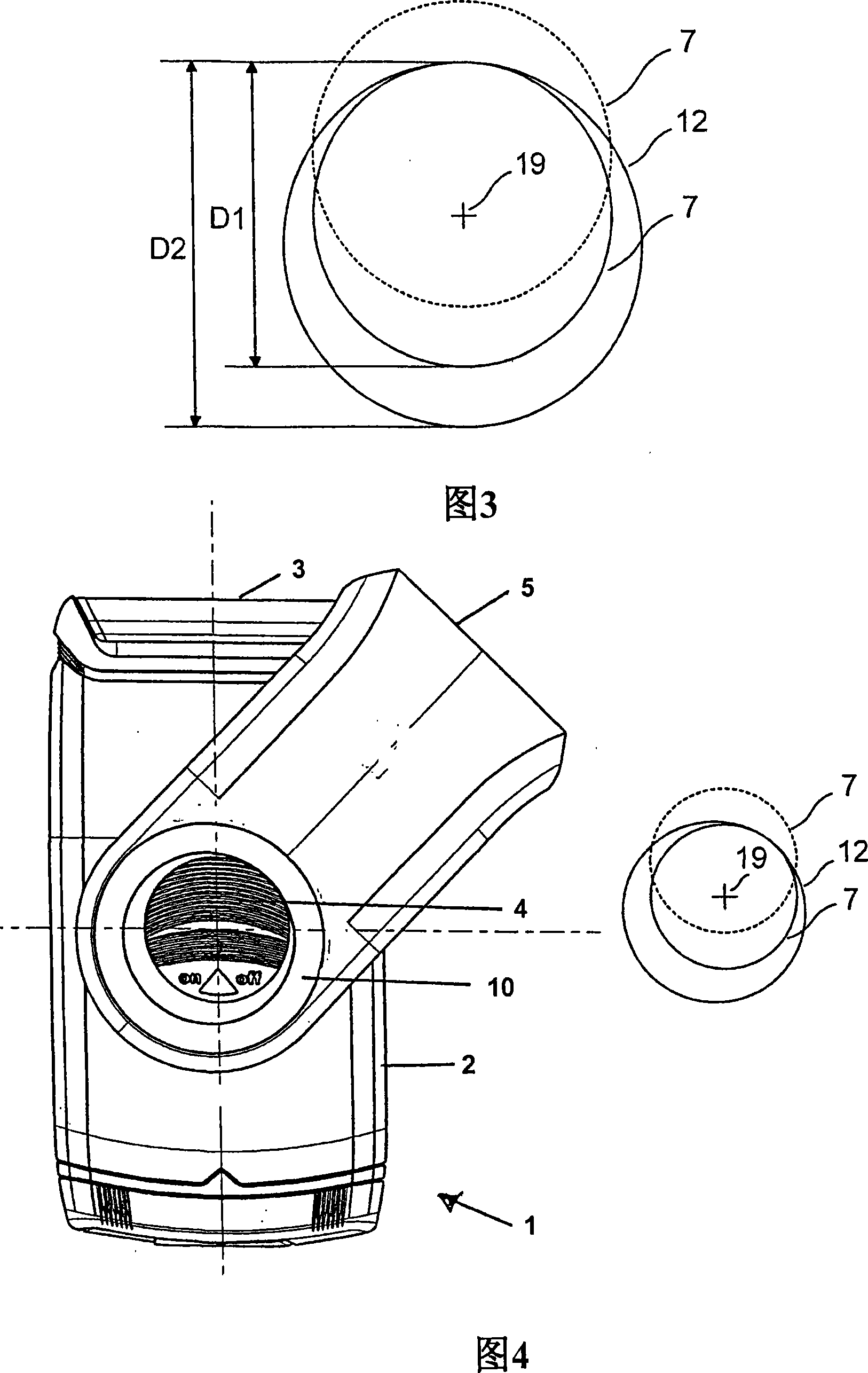
[0023] Figure 1 shows an embodiment of an electronic shaving device 1 constructed according to the invention in side view. FIG. 2 shows a longitudinal section through the center of the shaving device 1 . The shaving apparatus 1 is in particular a grid-independent device which can be operated with batteries or rechargeable batteries. The shaving device 1 is preferably constructed such that it can be easily carried on the go, for example. The internal design of the shaving device 1 is not shown here for the sake of clarity. As external elements, the shaving device 1 comprises in particular a housing 2 which can be hand-held, a shaving head 3 , a switching element 4 for operating switches not shown here and a protective cover 5 . Arranged in the shaving head 3 is a cutting system 6 which includes, for example, a shaving foil and a lower knife and is driven by an electric motor.

[0024] The switching element 4 is in the shape of a graduated disc, arranged on both main surfaces...


PUM


Abstract

An electric hair removal apparatus includes a housing adapted to be held in the hand, a guard cap mounted on the housing for pivotal movement about a pivot axis, and a control element with which a switch can be activated. The control element is arranged inside an at least locally circular recess of the guard cap. The pivot axis of the guard cap is constructed to be eccentric relative to the recess of the guard cap.

Description

technical field [0001] The present invention relates to an electric hair removal device and a method of operating an electric hair removal device. Background technique [0002] Such a hair removal device may be, for example, an epilator, a trimmer or a shaver. For the convenience of the user to use the hair removal device, it is possible to use batteries or rechargeable batteries independently of the power grid. However, this poses a risk that, for example, the battery or rechargeable battery will be drained if the user accidentally turns the hair removal device on while traveling with the hair removal device. One way to avoid this from happening is to lock the switch of the hair removal device in the off position. [0003] Thus, such as described in EP0 825 000B1, a dry shaving apparatus has a housing in which there is at least one electronic drive for at least one cutting system, at least one operating switch, and a protective cover for the cutting system, The protectiv...

Claims


Application Information

Patent Timeline
Patent Type & Authority Applications(China)
IPC IPC(8): B26B19/38A45D26/00
CPCA45D26/00B26B19/3853B26B19/382
Inventor 罗兰·乌尔曼
Owner BRAUN AG
Learn More