
Wellbore treatment apparatus and method

a treatment apparatus and wellbore technology, applied in the direction of borehole/well accessories, sealing/packing, survey, etc., can solve the problems of poor zonal isolation, major well construction problems, and stuck pipes

Inactive Publication Date: 2008-09-16
SCHLUMBERGER TECH CORP
View PDF9 Cites 5 Cited by
  • Summary
  • Abstract
  • Description
  • Claims
  • Application Information

AI Technical Summary

Benefits of technology

The invention provides an apparatus and method for treating wellbore instability by using a caliper with radially extending arms that can apply treatment fluid to regions of the wellbore. The caliper can be mounted on a wellbore conveyance tool and can be extended and retracted to engage with the wellbore. The treatment fluid can be delivered from the ends of the caliper arms to stabilize the wellbore. The technical effect of the invention is to provide a tool for effectively treating wellbore instability during well construction.

Problems solved by technology

In drilling the overburden, this phenomenon can lead to major well construction problems including stuck pipe and poor zonal isolation.
In a reservoir, the same problems can occur as in the overburden, but the additional inconvenience of sand production can also take place, sometimes throughout the life of the well.

Method used


Image

  • Wellbore treatment apparatus and method
  • Wellbore treatment apparatus and method

Examples


Embodiment Construction

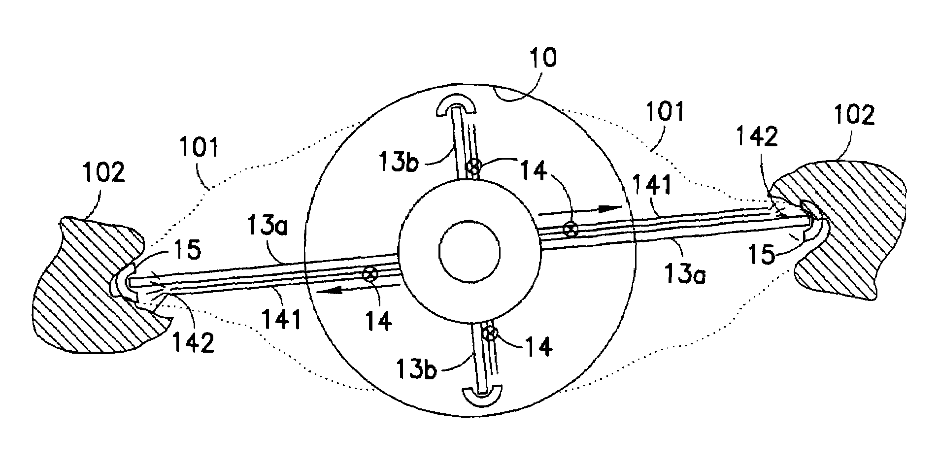
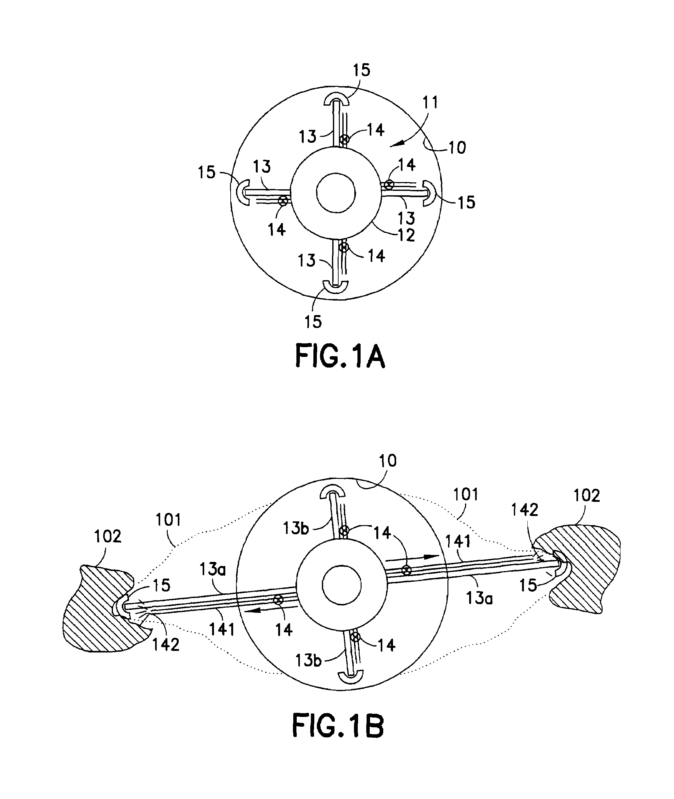
[0017]In FIG. 1A, a caliper 11 is rotatably mounted on a drill pipe or coiled tubing 12. The caliper 11 has a central hub and four equi-angularly spaced and radially extending arms 13, each of which is capable of extension and retraction in a radial direction. The arms 13 are biased towards their extended positions so that the radially outermost ends 15 of the arms engage the inner wall of a wellbore 10 being drilled, this bias conveniently being achieved by fluid pressure transmitted down the drill pipe or coiled tubing 12. The caliper hub and arms are free to rotate with respect to the drill pipe or coiled tubing 12 so that the caliper is capable of occupying an angular orientation independent of the drill pipe or coiled tubing. For this purpose, the caliper hub may be mounted on the drill pipe or coiled tubing by roller bearings.

[0018]The wellbore 10 is shown in-gauge (i.e. at the desired diameter) in FIG. 1A. However, wellbore instability can cause breakouts (i.e. enlargements i...


PUM


Abstract

A treatment apparatus and method for wellbore instability is described including a caliper with one or more radially extending arms which are capable of extending and retracting movement in a radial direction and a fluid supply facility to deliver treatment fluid from the ends of the arms to the wellbore wall, with a sensing and valve mechanism such that in use fluid is being delivered from the end of any extended arm to a breakout region of the wellbore where there is instability.

Description

BACKGROUND[0001]This invention relates to apparatus for and a method of treating wellbores, particularly treatments to reduce or prevent wellbore instability.[0002]Various caliper tools for gauging the diameter of a borehole are known in the art. In one example, a caliper tool includes one or more bow springs coupled to a tool body. When the tool body is disposed in a borehole, the bow spring engages the borehole wall and expands and contracts as the tool body traverses the borehole and the borehole diameter changes. The motion of the bow spring can provide an indication of the borehole diameter. In this case, a sensing device can be attached to the bow spring and used to monitor the motion of the bow spring. This is taught, for example, in U.S. Pat. Nos. 2,639,512 and 7,069,775 B2. Some caliper tools further include one or more rigid arms coupled between the tool body and the bow spring. The rigid arm deflects as the bow spring expands and contracts, and the motion of the rigid arm...

Claims


Application Information

Patent Timeline
Patent Type & Authority Patents(United States)
IPC IPC(8): E21B43/25E21B47/08
CPCE21B17/1021E21B47/08E21B33/138
Inventor REID, PAUL
Owner SCHLUMBERGER TECH CORP
Learn More