
Phase controller and cam shaft phase controller for internal combustion engine

a technology of phase controller and cam shaft, which is applied in the direction of valve drive, valve details, valve arrangement, etc., can solve the problems of complicated problem, insufficient driving force in advance direction, and difficulty in fitting the two, so as to improve the fuel economy in idle and increase the torque

Inactive Publication Date: 2008-09-16
HITACHI LTD
View PDF3 Cites 1 Cited by
  • Summary
  • Abstract
  • Description
  • Claims
  • Application Information

AI Technical Summary

Benefits of technology

Enables phase control over a wide range, improving fuel economy during idling and increasing torque in high-speed operations while preventing vibration and noise, ensuring a locked state without looseness under varying torque conditions.

Problems solved by technology

It is possible to rely on this frictional resistance torque if the direction of return to the locking position is one delay direction, but this driving force is not sufficient as a driving force in an advance direction in addition to the delay direction.
However, a varying torque based on a reaction force from a valve spring acts on a cam shaft and this makes the problem in question complicated.
The variation of torque acting on the cam shaft gives rise to the problem that in case of adopting a VTC phase locking means using a locking pin, if a locking pin—hole fitting gap is made too small, the fitting of the two becomes difficult, while if the gap is made too large, beating noise and damage are apt to occur due to looseness.
If the locking pin and the fitting hole are formed in a tapered shape, it seems possible to address the above problem that the fitting is difficult, but the pin axis and the hole axis cannot be made completely coincident with each other due to errors in parts dimensions and assembly (particularly it is impossible to make a radial deviation zero).
Moreover, the tapered shape causes a component of a force to be created in a direction to release the locking pin, with a consequent fear of occurrence of a new problem that the reliability of the locking function is impaired.

Method used


Image

  • Phase controller and cam shaft phase controller for internal combustion engine
  • Phase controller and cam shaft phase controller for internal combustion engine
  • Phase controller and cam shaft phase controller for internal combustion engine

Examples


first embodiment

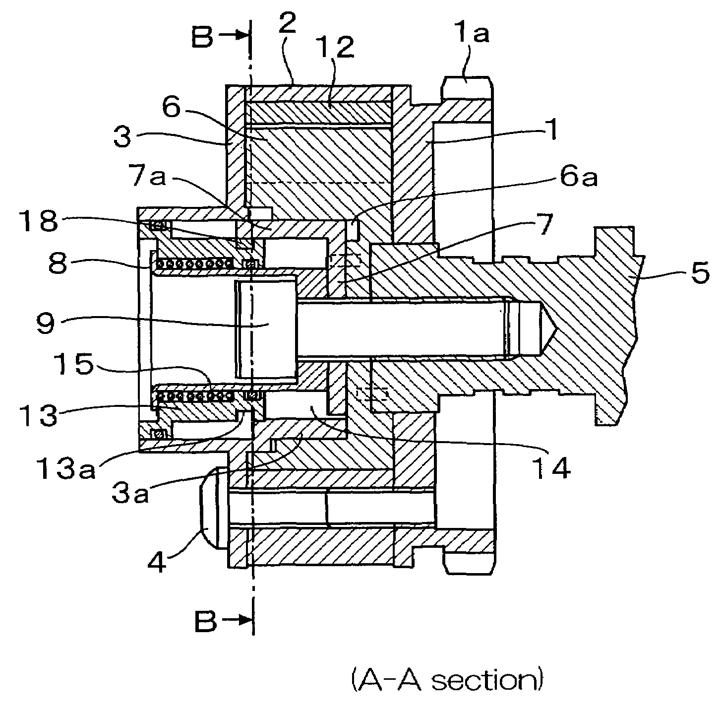
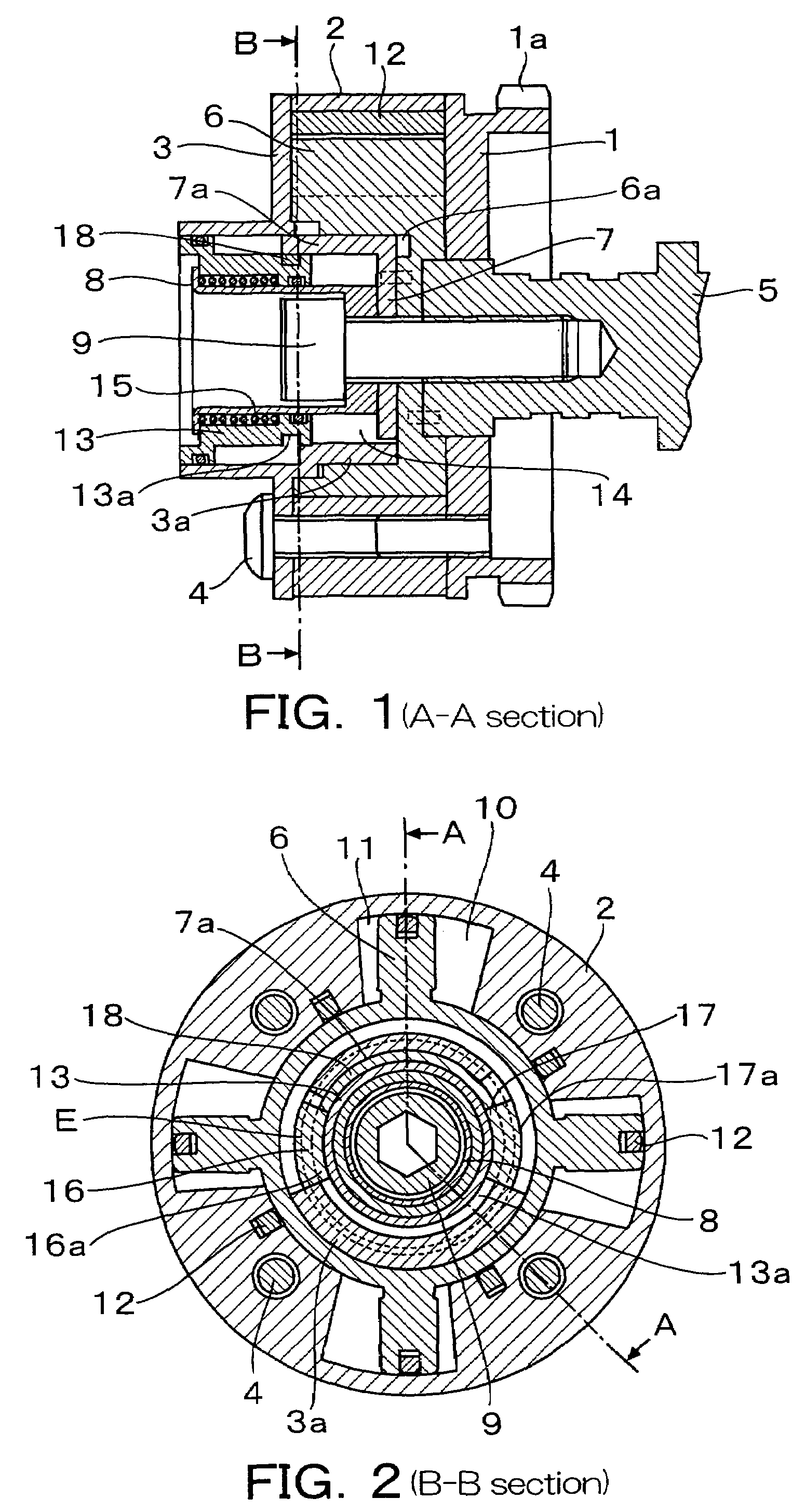
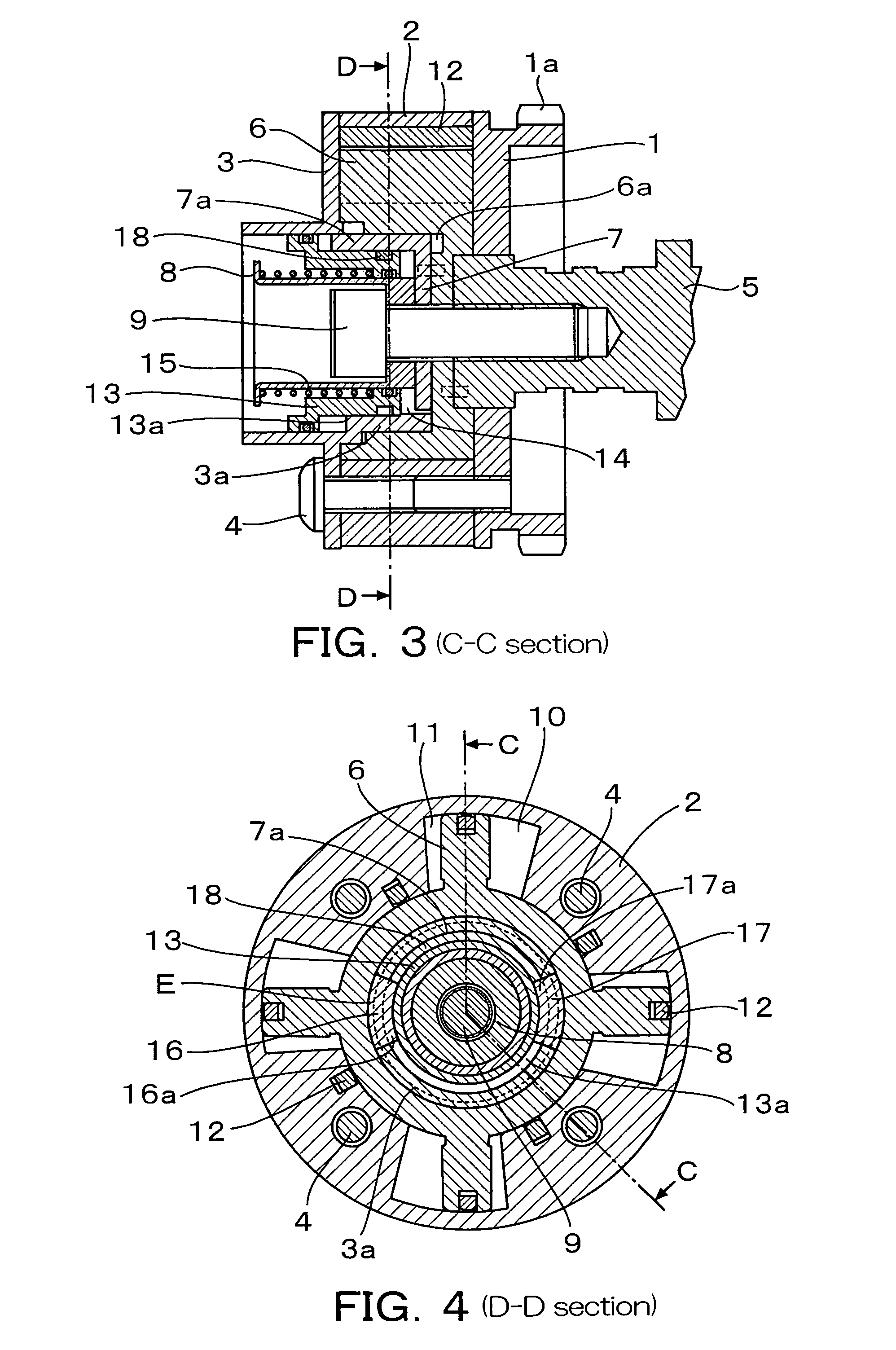
[0042]A phase controller (a cam shaft phase controller for an internal combustion engine as an example) having an intermediate position locking function according to a first embodiment of the present invention will be described in detail below with reference to FIGS. 1 to 5E. FIG. 1 is a sectional side view in an intermediate position unlocked state of a phase controller according to a first embodiment of the present invention, corresponding to a sectional view taken on line A-A in FIG. 2. FIG. 2 is a cross sectional view taken on line B-B in FIG. 1. FIG. 3 is a sectional side view in an intermediate position locked state of the phase controller of the first embodiment, corresponding to a sectional view taken on line C-C in FIG. 4. FIG. 4 is a cross sectional view taken on line D-D in FIG. 3. FIG. 5A to FIG. 5E comprise planarly developed sectional views of a circumference E in FIG. 2 or FIG. 4, illustrating intermediate position locking operations.

[0043]In FIG. 1 to FIG. 5E, a spro...

second embodiment

[0063]A cam shaft phase controller for an internal combustion engine having an intermediate position locking function according to a second embodiment of the present invention will be described in detail below with reference to FIG. 6 to FIG. 10(B). FIG. 6 is a sectional side view in an intermediate position unlocked state of a phase controller according to a second embodiment of the present invention, corresponding to a sectional view taken on line F-F in FIG. 7. FIG. 7 is a cross sectional view taken on line G-G in FIG. 6. FIG. 8 is a sectional side view in an intermediate position locked state of the phase controller of the second embodiment, corresponding to a sectional view taken on line H-H in FIG. 9. FIG. 9 is a cross sectional view taken on line I-I in FIG. 8. FIG. 10(A) and FIG. 10(B) comprise planarly developed sectional views of a circumference J in FIGS. 7 and 9, illustrating intermediate position locking operations. FIGS. 11, 12, 13, 14, and 15, illustrate a slant guide...


PUM


Abstract

A parallel guide portion as an integral structure of a sprocket and a vane, as well as a slant guide portion, are arranged alternately on the same circumference, with circumferential gaps being formed between said guide portion and the parallel guide portion, said guide portion having a shape such that the circumferential gaps become smaller in one axial direction of a cam shaft. Wedge members are disposed in the circumferential gaps respectively and are moved in one axial direction to fill up the circumferential gaps, thereby fixing the phase between the sprocket and the vane into a locked state. The wedge angle of each wedge member is set sufficiently small and, by utilizing varying torques acting on the cam shaft, said members are each moved and locked in one axial direction with a spring. Said members are actuated in an opposite axial direction with oil pressure to release the locked state, thereby permitting a phase angle control. By utilizing a varying torque acting on the cam shaft, the phase of the cam shaft is returned for itself to an intermediate position and is locked without looseness.

Description

BACKGROUND OF THE INVENTION[0001]1. Field of the Invention[0002]The present invention relates to a phase angle controller for controlling a phase angle between two rotary members. Particularly, the present invention is concerned with a phase changing device having a wide control range for realizing an optimum control position in a valve timing controller (hereinafter referred to as “VTC”) for an internal combustion engine which device makes variable an opening / closing timing of an intake valve or an exhaust valve actuated by an crank shaft through a cam shaft.[0003]2. Description of the Related Art[0004]First, a VTC used in an automobile engine will be outlined with reference to FIG. 16. In a four-stroke engine, sprockets mounted on front ends of cam shafts for intake and exhaust are rotated through a timing belt with rotation of a crank shaft. At this time, the cam shaft speed is reduced by half in accordance with a gear ratio. A VTC is mounted between each cam shaft and the associ...

Claims


Application Information

Patent Timeline
Patent Type & Authority Patents(United States)
IPC IPC(8): F01L1/34
CPCF01L1/34409F01L1/3442F01L1/024F01L2800/03F01L2001/34463F01L2001/34483F01L2001/34496F01L2001/34453
Inventor HAYASE, ISAOWATANABE, ATSUSHISUGA, SEIJIWATANABE, MASAHIKOICHINOSAWA, YOSHINORISAWADA, TAKANORI
Owner HITACHI LTD
Learn More