
Phoretic cell

a phoretic cell and a technology for displaying images, applied in the field of phoretic displays, can solve the problems of insufficient simple surface alignment treatment, inability to create threshold levels in devices, undesirable parasitic effects may conspire against the creation and correct positioning, etc., and achieve the effect of reducing the threshold level

Inactive Publication Date: 2008-09-09
HANNSTAR DISPLAY CORPORATION
View PDF8 Cites 0 Cited by
  • Summary
  • Abstract
  • Description
  • Claims
  • Application Information

AI Technical Summary

Benefits of technology

[0013]It is an object of the present invention to mitigate at least some of the disadvantages of the above phoretic display. It is a further object of the present invention to provide a method for achieving the preferred configuration of the liquid crystal suspension medium within the phoretic display.
[0015]The surface memory alignment layer provides a surface memory effect in order to provide the preferred configuration of the liquid crystal material within the present phoretic cell. Surface memory behaviour arises when a liquid crystal material is in contact with a solid surface and wherein the alignment of the liquid crystal in contact with the surface is reinforced by the continual diffusion of molecules in and out of the solid surface

Problems solved by technology

The defects create a threshold level in the device.
Notwithstanding the efficacy of the foregoing, circumstances may arise where a simple surface alignment treatment is insufficient to provide the preferred orientation of the liquid crystal material at the relief structure surface.
For example, depending upon the particular geometry of the relief structure surface, undesirable parasitic effects may conspire against the creation and correct positioning of defects sites within the phoretic cell.
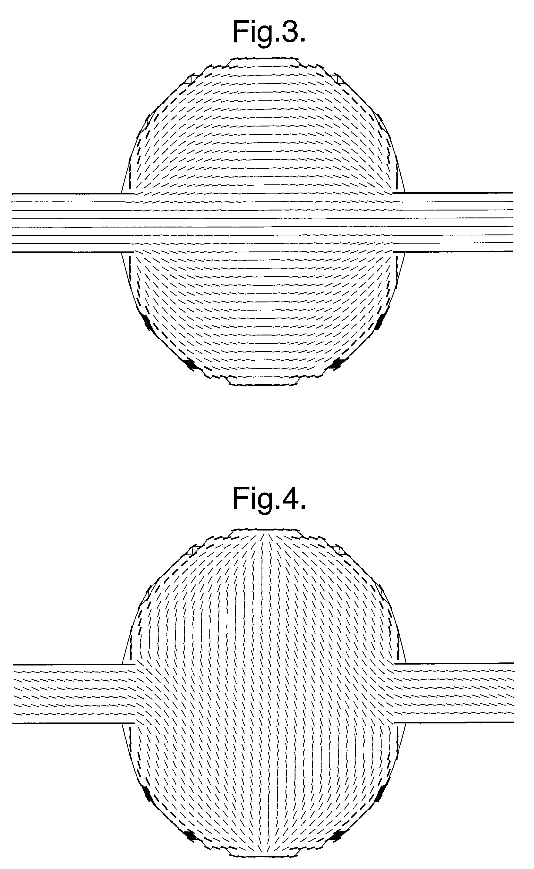
In particular, problems may be encountered in configurations where the preferred alignment of the liquid crystal material gives rise to strong localised distortions of the liquid crystal director.
The distortions within the liquid crystal director create a high degree of elastic or defect energy within the material which can lead to instability of the configuration and to the potential failure of the display.

Method used


Image

  • Phoretic cell
  • Phoretic cell
  • Phoretic cell

Examples


Embodiment Construction

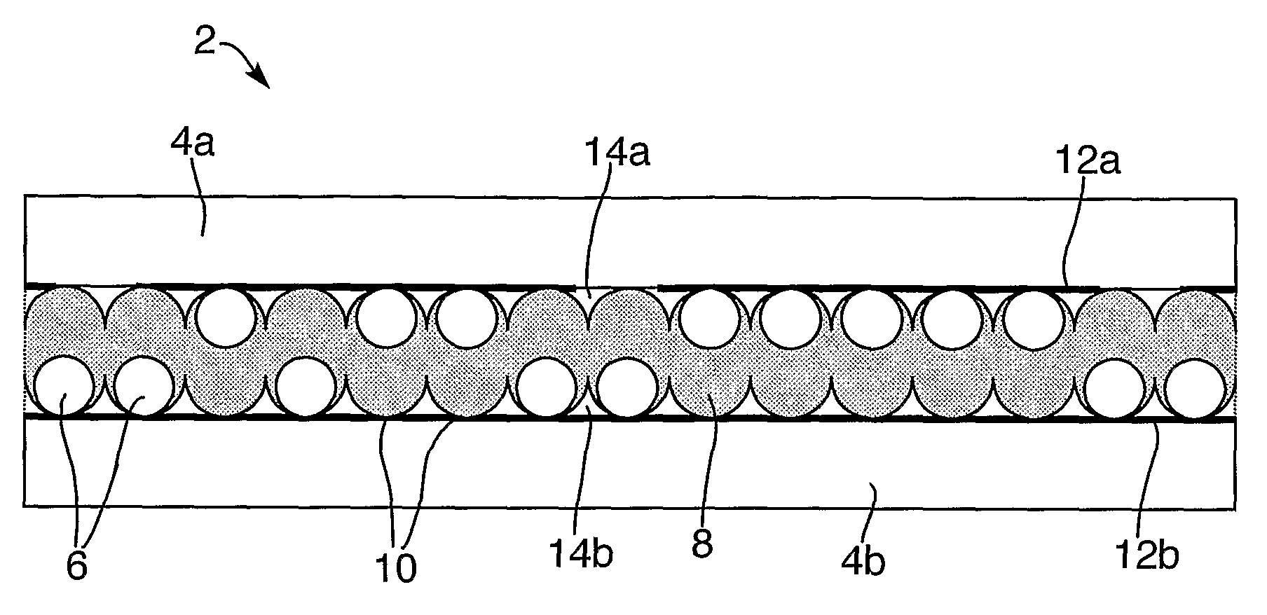
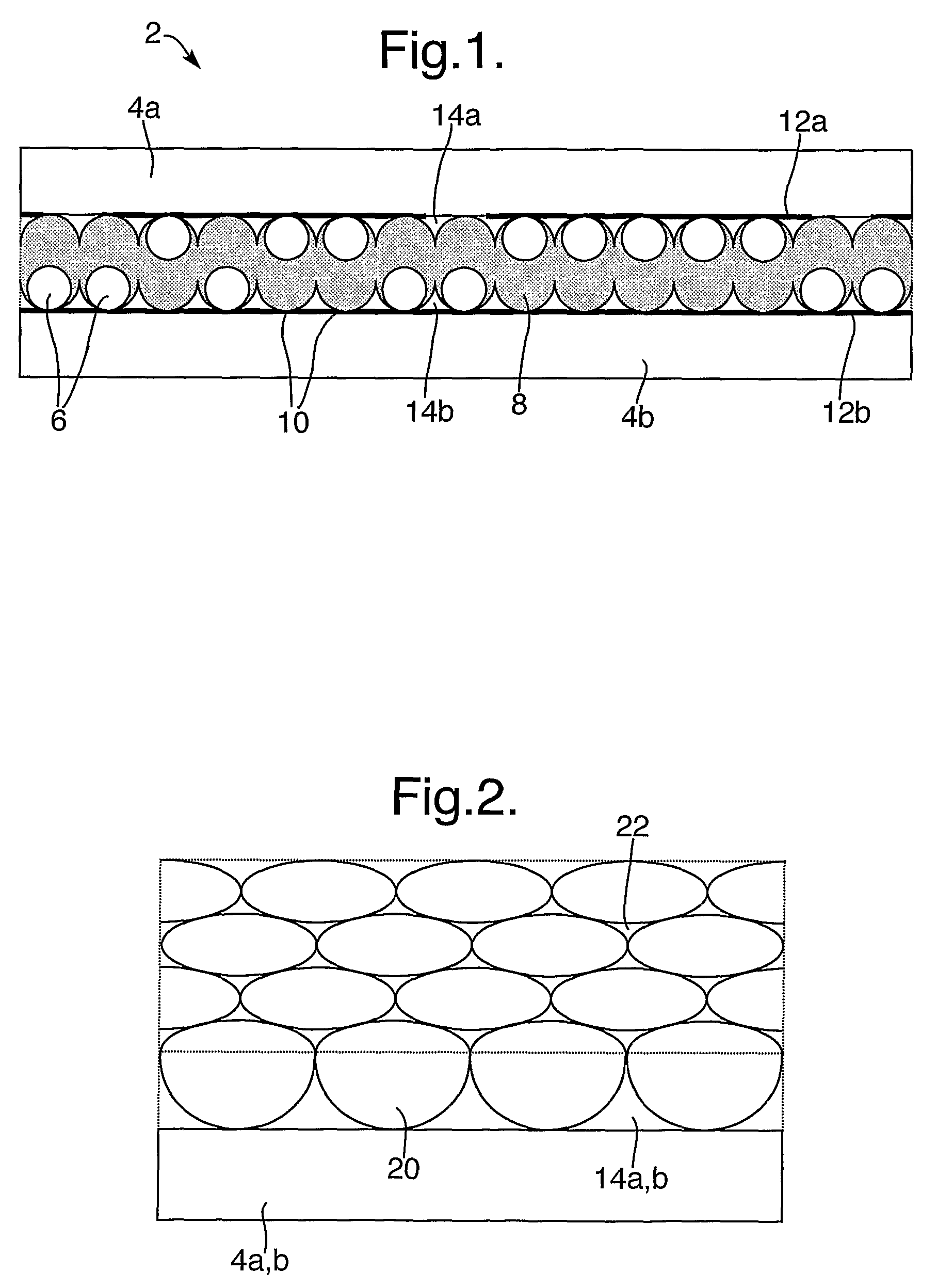
[0053]Referring to FIG. 1, an electrophoretic display 2 comprises an electrophoretic cell in which particles of an electrophoretic material 6 are suspended in a suspension medium 8 comprising a liquid crystal material. The particles of electrophoretic material have an electrical charge associated therewith when suspended in this manner. Application of an electric field to the cell causes the charged particles to move therein under the influence of the applied electric field. The geometry of the system is arranged to promote defects 10 within the liquid crystal material.

[0054]The above mentioned electrophoretic cell and electrophoretic display are described in further detail in patent application PCT / GB03 / 003512.

[0055]The operation of the electrophoretic display is described briefly hereunder by way of background to the present invention.

[0056]In the above configuration, the presence of the particles of electrophoretic material 6 distorts the alignment of the liquid crystal material ...


PUM

PropertyMeasurementUnit
surface energyaaaaaaaaaa
relief structureaaaaaaaaaa

Abstract

A relief structure alignment layer comprising a relief structure surface incorporating at least one indentation, the at least one indentation having an internal surface extending from the relief structure surface, wherein the relief structure alignment layer has a surface memory alignment layer arranged to impart a preferred liquid crystal director alignment to a liquid-crystal material in contact therewith as well as methods for configuring a liquid crystal material within a cell having a relief structure alignment layer by applying at least one of an electric field and a magnetic field and phoretic displays comprising at least on relief structure alignment layer.

Description

BACKGROUND OF THE INVENTION[0001](1) Field of the Invention[0002]The present invention relates to a phoretic display incorporating a liquid crystal suspension medium having a preferred configuration therein and to a method of achieving the preferred configuration of the liquid crystal suspension medium within the phoretic display. Such a phoretic display may be used in a wide range of electronic consumer goods, for example household electrical and electronic items, mobile telephones, personal computers, electronic personal organizers, e-books etc.[0003](2) Description of the Art[0004]Phoretic displays typically comprise a suspension layer containing finely divided phoretic particles dispersed within a liquid suspension medium. The spatial distribution of the phoretic particles within the suspension layer may be altered by applying a magnetic or electric field to the device. The particles migrate within the device under the influence of the applied field.[0005]A phoretic display devi...

Claims


Application Information

Patent Timeline
Patent Type & Authority Patents(United States)
IPC IPC(8): G09G3/36G02F1/1333G02F1/1337G02F1/167
CPCG02F1/1337G02F1/133707G02F1/167G02F2001/133765G02F2001/133742G02F1/133711G02F1/133742G02F1/133765
Inventor MILLER, RICHARD JONATHANVOTTE, ISABELLE MARIANNE
Owner HANNSTAR DISPLAY CORPORATION
Learn More