
Sump grate for a swimming pool

a technology for swimming pools and sump grates, which is applied in swimming pools, filtration separation, separation processes, etc., can solve the problems of human body being trapped on the top of the cover and the inability to remove the body of the person

Active Publication Date: 2008-09-02
HYDROTECH A CALIFORNIA
View PDF13 Cites 26 Cited by
  • Summary
  • Abstract
  • Description
  • Claims
  • Application Information

AI Technical Summary

Benefits of technology

[0003]The example of the following sump is shown and claimed in a copending application Ser. No. 11 / 207,153. The sump is fabricated quite differently from the known sumps in that the sump is injection molded instead of being fabricated from PVC sheets. The sump has a tapered body which considerably increases the strength of the body and which allows a multiple of bodies to be stacked into each other for storage and for shipping.

Problems solved by technology

It has been found, that in many instances, the force of the suction is of such intensity that a human body can be trapped on top of the cover and the body of the person cannot be removed unless emergency procedures are undertaken.

Method used


Image

  • Sump grate for a swimming pool
  • Sump grate for a swimming pool
  • Sump grate for a swimming pool

Examples


Embodiment Construction

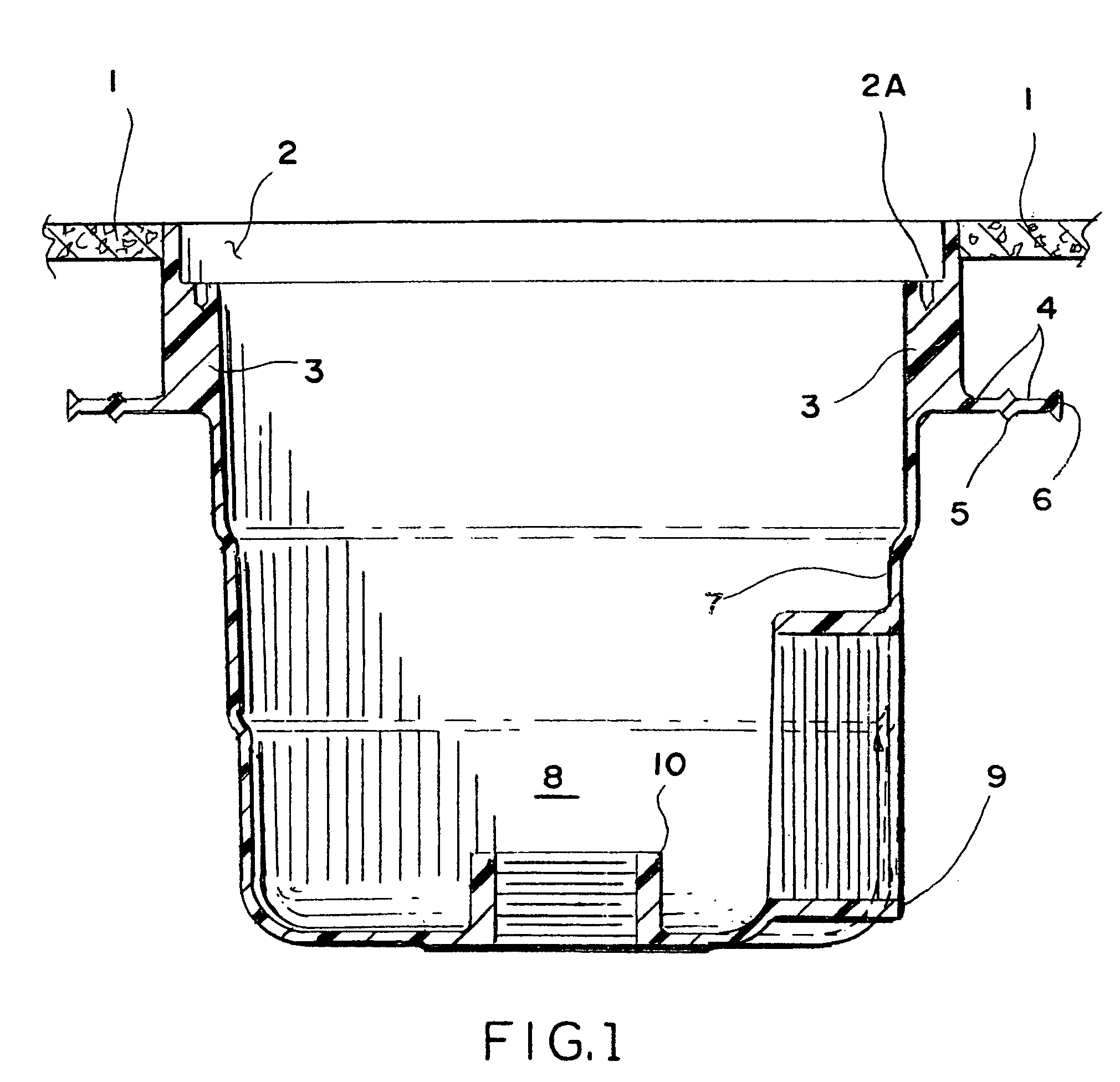
[0009]FIG. 1 shows a sump in a cross section as it is installed in concrete 1 flush with the surface of the concrete 1. The top of the sump has a recess 2 to receive the inventive grate therein to be fastened into the recess 2 by way of screws that are driven into the pilot holes 2A. The upper part or section of the sump has thickened side wall 3 to give it added strength. Just below the thickened side wall 3 there is a laterally extending disc 4 which surrounds the body of the sump. In the middle and at the end or periphery of the disc there are upper and lower ridges 5 and 6 which act as water stops once the sump is installed within the concrete of the pool. These water stops are accomplished by way of the ridges 5 and 6 which present an obstacle to any water trying to pass there over.

[0010]As mentioned above, the body of the sump is tapered by way of several sections to render the same stackable and to act as reinforcements once installed in concrete. There is a thickened upper s...


PUM

PropertyMeasurementUnit
thicknessaaaaaaaaaa
thicknessaaaaaaaaaa
sizeaaaaaaaaaa

Abstract

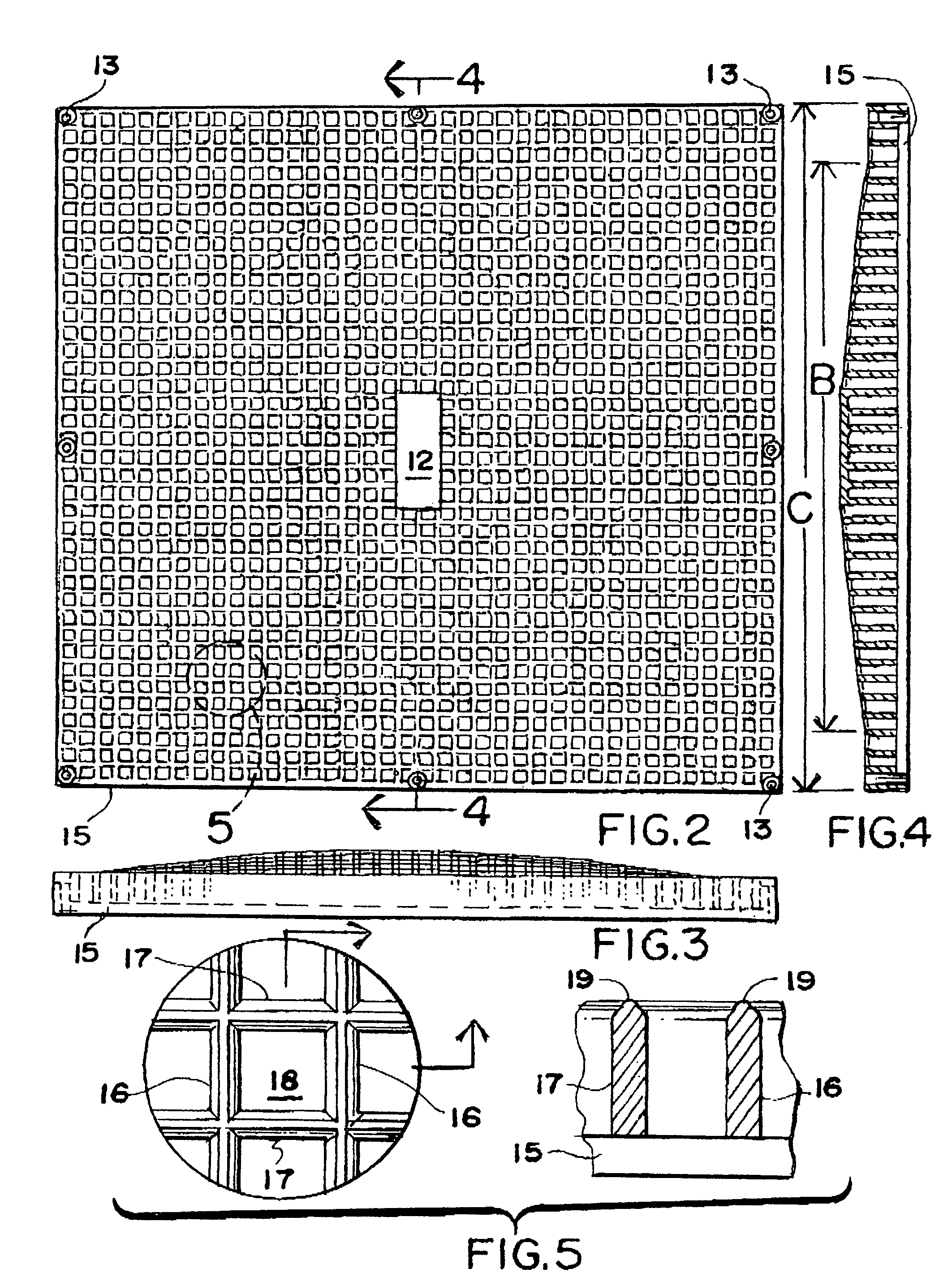
A grate cover in combination with a swimming sump being installed in a recess in the top of the sump. The grate cover having a multiple of interstices or openings there through. The size of the interstices being held to a minimum so that fingers of a human cannot be sucked into the openings. The top surface of the grate cover has a curvature thereon while the bottom surface is flat. This way, the forceful suction within the sump cannot obtain enough force to suction the skin of a human against the grate cover to cause any injuries.

Description

FIELD OF THE INVENTION[0001]Most all swimming pools have a drainage sump located mostly in the deep end bottom of the pool for draining the pool when necessary and also for participating in the circulation in the pool water which is circulating through the filter system.BACKGROUND OF THE INVENTION[0002]The above mentioned sump is of a pot-like configuration and has a grating installed over the opening to prevent any of larger debris from entering into the sump and to prevent any contact of the human limbs with the considerable suction force in the bottom of the sump to avoid any injury. Most of the sump covers known in the art have a flat surface and the covers have many interstices therein to catch anything on the flat surface thereon while the water is suctioned into the sump. It has been found, that in many instances, the force of the suction is of such intensity that a human body can be trapped on top of the cover and the body of the person cannot be removed unless emergency pro...

Claims


Application Information

Patent Timeline
Patent Type & Authority Patents(United States)
IPC IPC(8): E04H4/16
CPCE04H4/1227E04H4/1218
Inventor LAWSON, ROBERT B.
Owner HYDROTECH A CALIFORNIA
Learn More