
Method and apparatus for suppressing sparks

a technology of suppressor and spark, which is applied in the direction of separation process, colloidal chemistry, dispersed particle separation, etc., can solve the problems of affecting the effect of spark extinguishing, sparks in this size range may travel relatively long distances, sparks may move, etc., to achieve the effect of effectively extinguishing sparks, reducing the number of sparks, and easy installation

Active Publication Date: 2008-08-26
BLENDER PROD
View PDF17 Cites 16 Cited by
  • Summary
  • Abstract
  • Description
  • Claims
  • Application Information

AI Technical Summary

Benefits of technology

"The present invention provides a spark suppression device that can effectively extinguish sparks in industrial processes. The device takes advantage of various thermo-fluid principles to extinguish sparks, including disruption of the spark ember / hot air bubble equilibrium and the sling-shot effect. The device includes a static mixing portion or tubulator that is mounted within the duct of the air handling system upstream of the filter media. The device extinguishes sparks by taking advantage of increased pressure and physical contact with the blades of the device. The invention helps to manage sparks in air handling systems and prevent damage to filter media and other components."

Problems solved by technology

Nevertheless, some sparks are indeed large enough and hot enough to be conveyed through ductwork for relatively long distances.
Because spark embers are buoyant due to a bubble or casing of hot air that surrounds each spark, sparks in this size range may travel relatively long distances in ductwork.
Thus, sparks may move at velocities that substantially match the air stream, until the spark is arrested against the filter media.
If a spark is large enough and hot enough, the filter media will ignite, and so too will combustible dust caked on the filter media.
A spark passing through the spark suppressor is subjected to a sudden increased pressure that disrupts the hot air bubble surrounding the spark ember.
Accordingly, the ember / hot air bubble equilibrium is disrupted under the influence of increased pressure and becomes unstable, and the spark ember begins to separate from the hot air bubble.

Method used


Image

  • Method and apparatus for suppressing sparks
  • Method and apparatus for suppressing sparks
  • Method and apparatus for suppressing sparks

Examples


Embodiment Construction

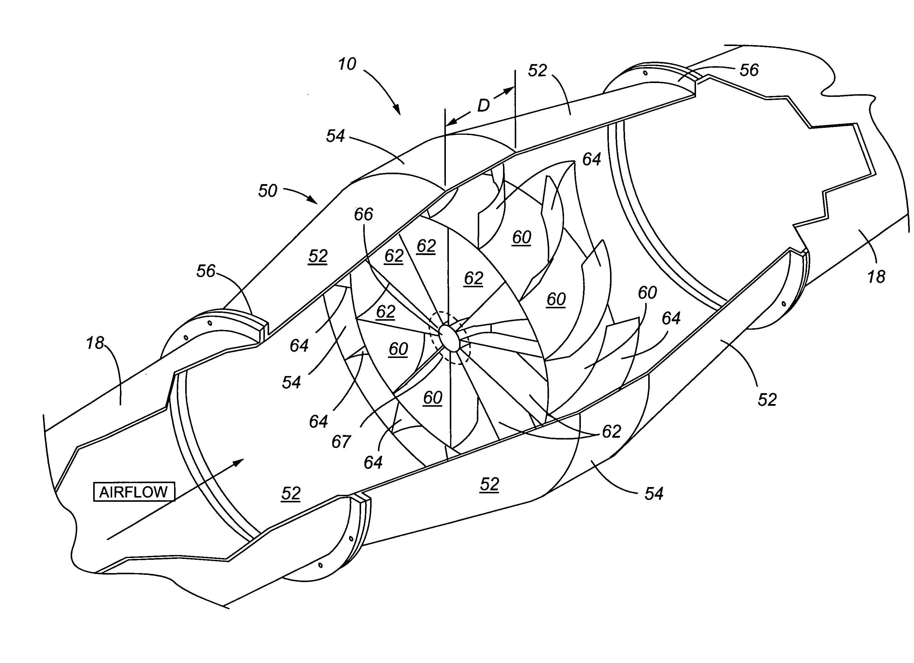
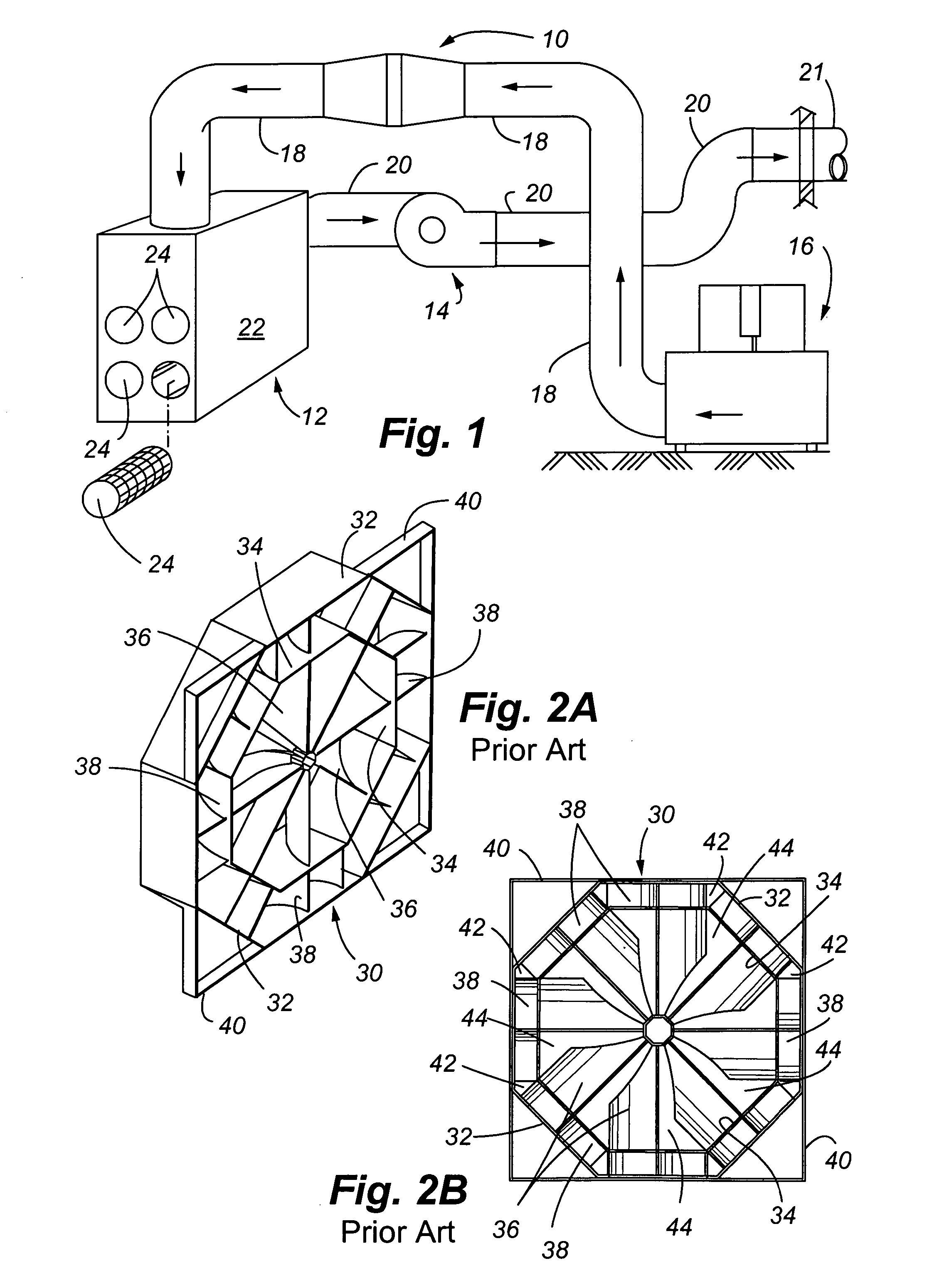
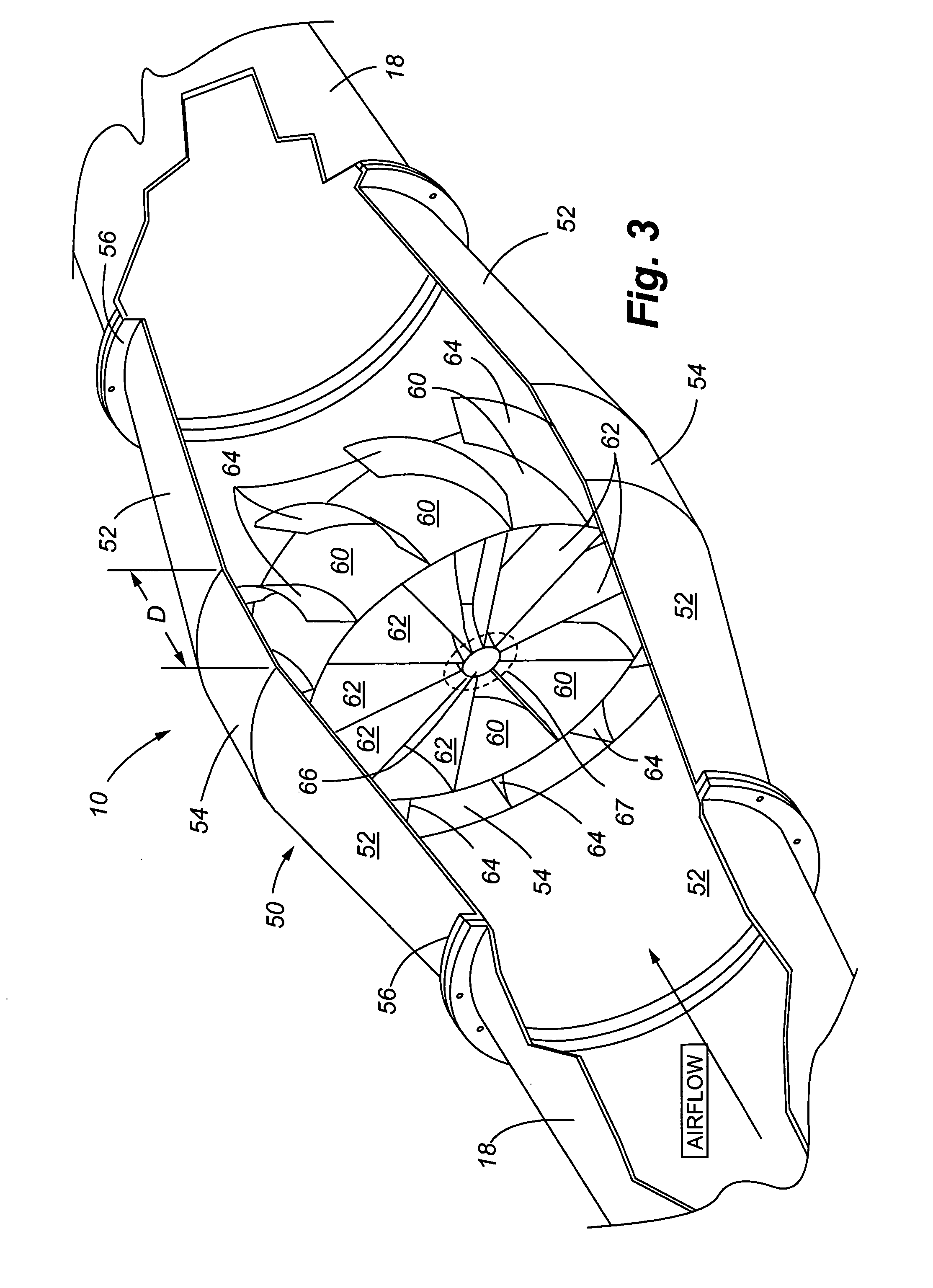
[0026]Referring to FIG. 1, the spark suppressor 10 of the present invention is illustrated as being installed within an air handling system. A typical air handling system includes the machine / process 16 which generates sparks, either actively, passively or accidentally, and a filtration inlet line / duct 18 which conveys contaminated air and sparks to a filtration unit 12. The filtration unit 12 includes a filter housing 22, and one or more filter elements 24. In this particular system, the filter elements 24 are shown as cartridge-type filters, which are replaced periodically over time as they become clogged / caked over with particulate. A filtration outlet line / duct 20 allows conveyance of filtered air back into the environment through discharge exit duct 21. A fan 14 draws the airstream through the filtration unit. The fan 14 is representative of any standard process fan providing enough power to draw air-flow through the system and to thereby draw particulate away from the machine / ...


PUM

PropertyMeasurementUnit
sizeaaaaaaaaaa
diameteraaaaaaaaaa
velocityaaaaaaaaaa

Abstract

A spark suppression device includes a plurality of blades or vanes that are mounted transversely in a duct of an air handling / dust collection system communicating with a spark source. A controlled flow of air carries sparks from the spark source through the spark suppression device. Sparks are suppressed by turbulence created in the airstream from the blades that have a downstream curvature. The turbulence strips away a hot air bubble surrounding a spark ember, thereby effectively cooling the spark and significantly reducing combustion at the spark ember. Other attributes of the invention contributing to spark suppression include an overlapping arrangement of the blades that results in high-velocity impact of the sparks against the blades, thereby breaking up the spark embers into smaller embers, and creation of rapid increased pressure within the spark suppression device that also helps to strip away the spark ember from the surrounding hot air bubble.

Description

FIELD OF THE INVENTION[0001]The present invention relates to devices that manage, control, or suppress sparks, and more particularly, to a method and apparatus for suppressing sparks that are produced in industrial processes and become conveyed in air handling systems and dust collection systems.BACKGROUND OF THE INVENTION[0002]There are many industrial processes that result in the production of sparks, either actively, passively or accidentally. Active production of sparks include those processes that generate a tremendous quantity of sparks, for example, welding and plasma cutting operations. Passive production of sparks refers to processes that are known to periodically generate sparks, yet spark production is relatively infrequent, for example a drying process that produces sparks primarily during startup and shutdown periods of operation. Accidental spark production refers to spark generation as the result of an accidental occurrence, for example, sparks are generated by the im...

Claims


Application Information

Patent Timeline
Patent Type & Authority Patents(United States)
IPC IPC(8): B01D50/00A62C99/00
CPCA62C3/04B01D50/00B01D46/0093Y10S55/20
Inventor LINDGREN, ROSS A.IRVINE, WILLIAM O.
Owner BLENDER PROD
Learn More