Vehicle seat lifting unit

Inactive Publication Date: 2008-08-19
AUTECH JAPAN INC
View PDF21 Cites 15 Cited by
  • Summary
  • Abstract
  • Description
  • Claims
  • Application Information

AI Technical Summary

Benefits of technology

[0010]Considering the above-mentioned conventional problems, an object of the present invention is to provide a highly convenient seat lifting unit that is easy to install in a vehicle having a narrow indoor width.

Problems solved by technology

However, the conventional seat lifting unit is difficult to install in a vehicle having a narrow indoor width because each of the two pairs of lift arms occupy a space on one of lateral sides of the vehicle occupant seat.
In addition, the conventional seat lifting unit fails to accomplish effective use of the vehicle occupant compartment because the lift arms remain occupying the space on each of the lateral sides of the vehicle occupant seat when the backrest takes a backwardly reclined position.

Method used


Image

  • Vehicle seat lifting unit
  • Vehicle seat lifting unit
  • Vehicle seat lifting unit

Examples


Embodiment Construction

[0025]Selected embodiments of the present invention will now be explained with reference to the drawings. It will be apparent to those skilled in the art from this disclosure that the following descriptions of the embodiments of the present invention are provided for illustration only and not for the purpose of limiting the invention as defined by the appended claims and their equivalents.

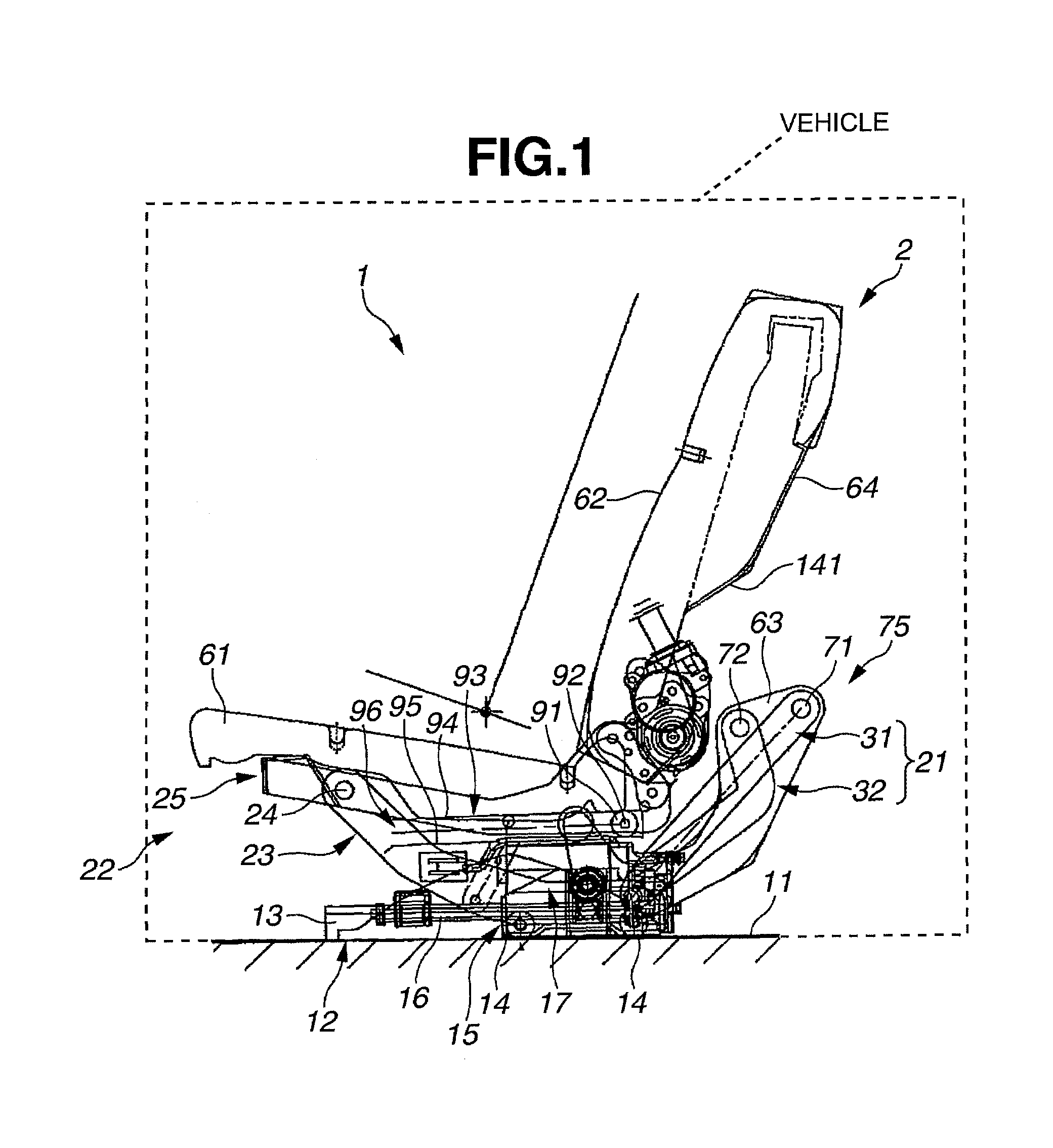
[0026]Referring to initially to FIGS. 1 and 7, a vehicle seat lifting unit 1 is illustrated in accordance with a first embodiment of the present invention. Basically, the vehicle seat lifting unit 1 includes a vehicle seat 2 that is moveable from an initial position (see FIG. 1) inside a vehicle occupant compartment to a displaced position (see FIG. 6) outside of the vehicle occupant compartment. Thus, the seat lifting unit 1 is constructed and arranged so as to lower or lift a vehicle seat 2 during its movement between the initial position (see FIG. 1) inside the vehicle occupant compartment and t...


PUM


Abstract

A vehicle seat lifting unit is provided with a slider and a lift arm assembly that are driven by a drive unit to move a seat with a seat holder between an initial position inside the vehicle occupant compartment and a displaced position outside the vehicle occupant compartment that is lower than the initial position. The lift arm assembly has a pair of arms that cooperate with the slider and the seat holder to form a linkage mechanism. The drive unit moves the slider along the predetermined path between an advance position and a retreat position and causes the first and second arms of the lift arm assembly to selectively swing from backwardly tilted positions to forwardly tilted positions, which in turn selectively shifts the seat between the initial position and the displaced position outside the vehicle occupant compartment that is lower than the initial position.

Description

CROSS-REFERENCE TO RELATED APPLICATIONS[0001]This application is related to Japanese Patent Application No. 2005-292545, filed on Oct. 5, 2005. The entire disclosure of Japanese Patent Application No. 2005-292545 is hereby incorporated herein by reference.BACKGROUND OF THE INVENTION[0002]1. Field of the Invention[0003]The present invention generally relates to seat lifting units for vehicles.[0004]2. Background Information[0005]Conventionally, seat lifting units are used to lower or lift a vehicle seat through a vehicle door opening. A known seat lifting unit of the above kind is described in Japanese Laid Open Patent Publication No. 2001-001812A.[0006]This known seat lifting unit has a function to lower a vehicle seat from an initial position inside a vehicle occupant compartment to a displaced position outside the vehicle occupant and lift the vehicle seat from the displaced position to the initial position. The vehicle seat is retained by a seat holder. The seat holder includes t...

Claims


Application Information

Patent Timeline
IPC IPC(8): B60N2/02
CPCB60N2/245
Inventor FUKUI, OSAMUFUJIKURA, HIROKI
Owner AUTECH JAPAN INC
Why Eureka
Try Eureka