
Modeling system for graphic user interface

Active Publication Date: 2008-08-12
SAP PORTALS ISRAEL
View PDF8 Cites 86 Cited by
  • Summary
  • Abstract
  • Description
  • Claims
  • Application Information

AI Technical Summary

Benefits of technology

[0010]An embodiment of the present invention relates to a system for modeling user interfaces in understandable terms, so that user interface designs can be easily read and communicated. Such a system preferably should be expressive enough to enable the modeling of arbitrarily complex and dynamic user interfaces. More preferably, the system should enable the automatic translation of user interface models to executable code, so that the laborious and error prone programming processes can be skipped.
[0026]The user interface modeling system described herein provides numerous benefits. The system is declaratively closed so that all the different aspects of a user interface can be expressed purely in declarative terms of the modeling language. The system provides a representation simple enough to be read and communicated by humans. The system is computationally tractable, thus enabling automated validation, simulation, and generation of working user interfaces from valid models. The system has the capacity for declaring elastic user interface models that withstand variations in the context of use while preserving usability. The system encourages modifiability and not enforce any particular development strategy. The system enables a strong parallel architecture, both within and across contexts of use. The system enables a knowledge-based storage mechanism for its representation. The system allows for extensions to various aspects of the user interface models it represents.

Problems solved by technology

The construction and maintenance of user interfaces is becoming a central problem for large, complex systems.
With the advent of new technologies and user-centered concerns, the user interface portion of interactive systems is becoming increasingly large and costly.
All these factors, and more, make user interfaces hard to design and implement.
However, none of these methods has been widely adopted.
Development organizations resist formal specifications because they are difficult to understand, are not expressive enough, are usually not executable, and therefore, are viewed as unnecessary additional work.

Method used


Image

  • Modeling system for graphic user interface
  • Modeling system for graphic user interface
  • Modeling system for graphic user interface

Examples


Embodiment Construction

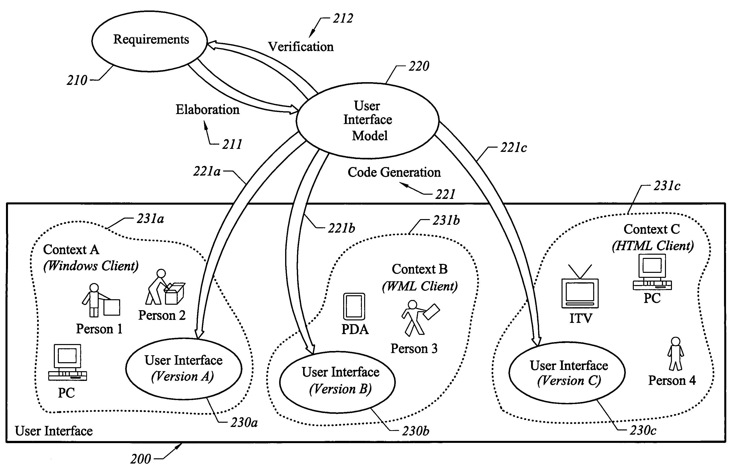
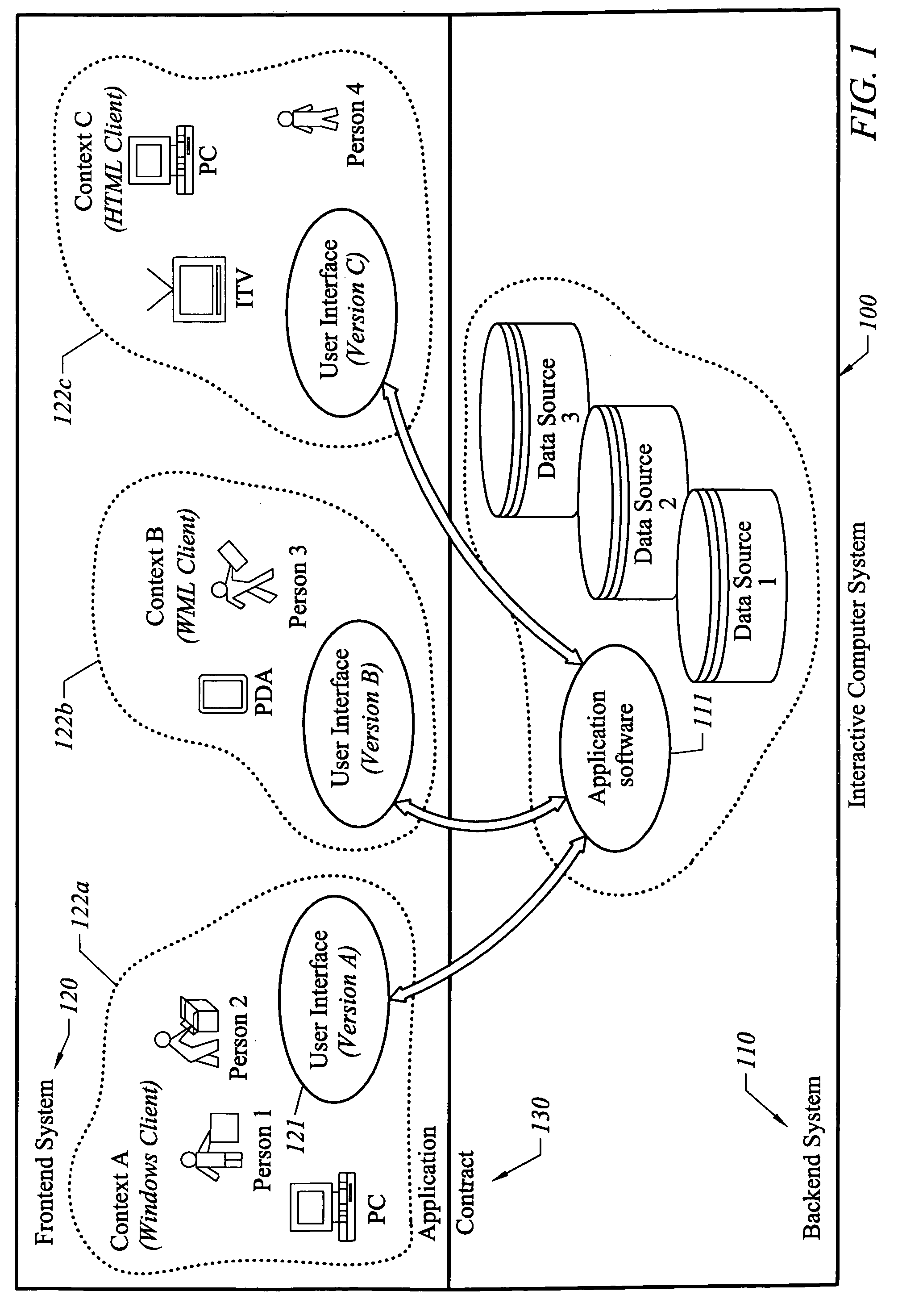
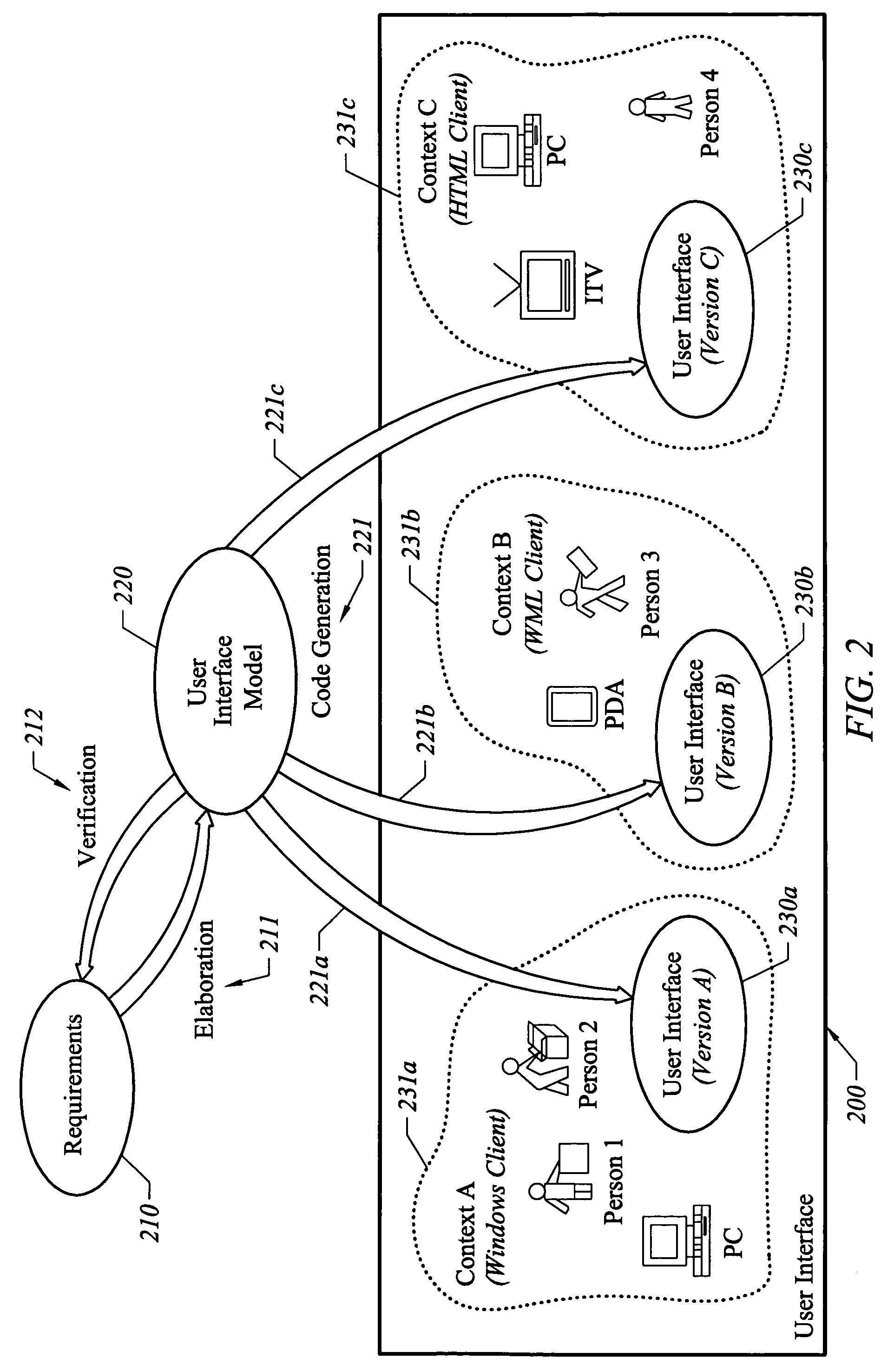
[0053]The present invention relates to a modeling system or visual tool for creating a user interface (UI) without writing code. The system provides a means for defining user interfaces, including highly complex and dynamic user interfaces, in a manner that is independent of any implementation context. In a preferred embodiment of the invention, the modeling system leads from a user-friendly visual representation of the user interface, through progressively detailed specifications of structural and behavioral aspects of the user interface parts, until a rigorous definition of the user interface in its contexts of use is achieved. Using a visual representation of UI created by a designer, the modeling system automatically generates fully working user interface code.

[0054]FIG. 1 illustrates a generalized diagram of an interactive computer system in a client-server environment. An interactive computer system (server) 100 serves an application to one or more users (clients) and can be g...


PUM


Abstract

A modeling system for universal specification of user interfaces. The system provides a means for defining user interfaces, including highly complex and dynamic user interfaces, in a manner that is independent of any implementation context. The modeling system leads from a user-friendly visual representation of the user interface, through progressively detailed specifications of structural and behavioral aspects of the user interface parts, until a rigorous definition of the user interface in all its contexts of use is achieved. Using the information captured in the model, tools that automatically generate the fully working user interface code can be built.

Description

CROSS-REFERENCES TO RELATED APPLICATIONS[0001]The present application claims priority from U.S. Provisional Patent Application No. 60 / 426,097, filed on Nov. 14, 2002, and U.S. Provisional Patent Application No. 60 / 479,017, filed on Jun. 16, 2003, both of which are incorporated by reference.BACKGROUND OF THE INVENTION[0002]The present invention relates to the field of human-computer interaction, and in particular to user interface modeling.[0003]The construction and maintenance of user interfaces is becoming a central problem for large, complex systems. User interfaces are the bridge between applications and users, and, as a result, have to cope with the complexities of both. With the advent of new technologies and user-centered concerns, the user interface portion of interactive systems is becoming increasingly large and costly.[0004]Faster and more capable machines and networks are providing users with more functionalities and more information, but at the same time are overwhelming...

Claims


Application Information

Patent Timeline
IPC IPC(8): G06F3/00G06F9/40G06F9/44G06F40/143
CPCG06F8/38G06F9/4443G06F3/048G06F3/0484G06Q10/067G06F9/451G06F40/143G06F40/103G06F40/146G06F40/166G06F40/197G06F3/0482G06F2203/04803
Inventor GILBOA, YUVAL
Owner SAP PORTALS ISRAEL
Learn More