
Apparatus employing conically parallel beam of X-rays

a conically parallel beam and apparatus technology, applied in the field of xray apparatus, can solve the problems of inefficient current systems, difficult to measure low levels, and difficult to reduce the effect of radiation intensity

Inactive Publication Date: 2008-08-12
OHARA DAVID
View PDF1 Cites 37 Cited by
  • Summary
  • Abstract
  • Description
  • Claims
  • Application Information

AI Technical Summary

Benefits of technology

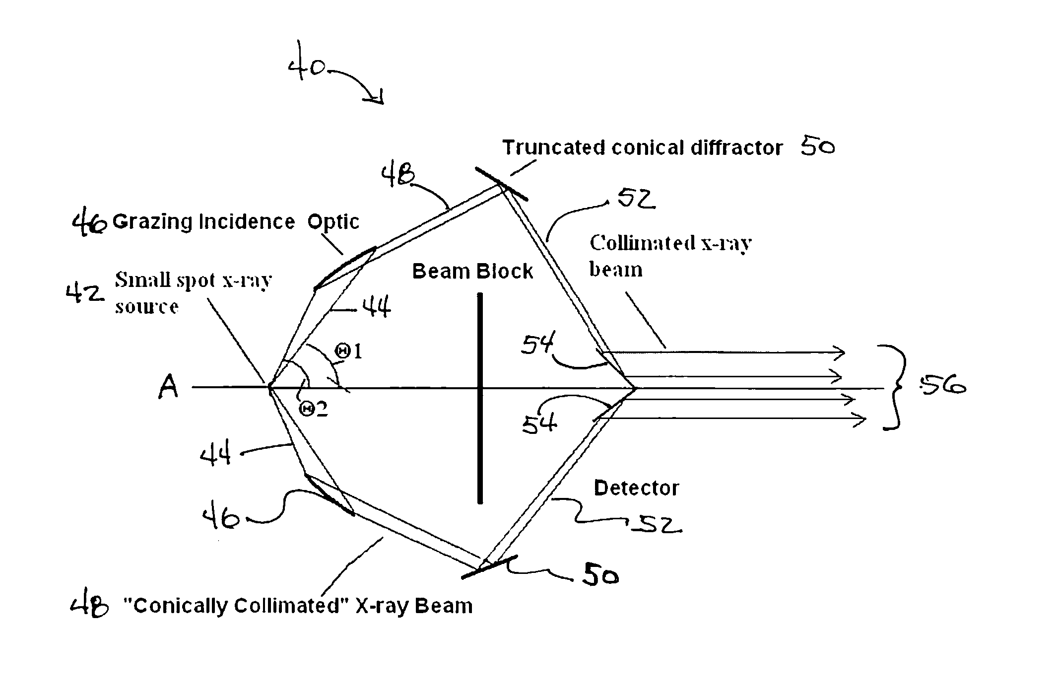
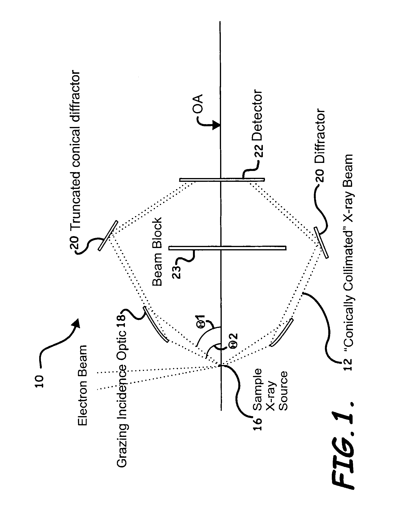
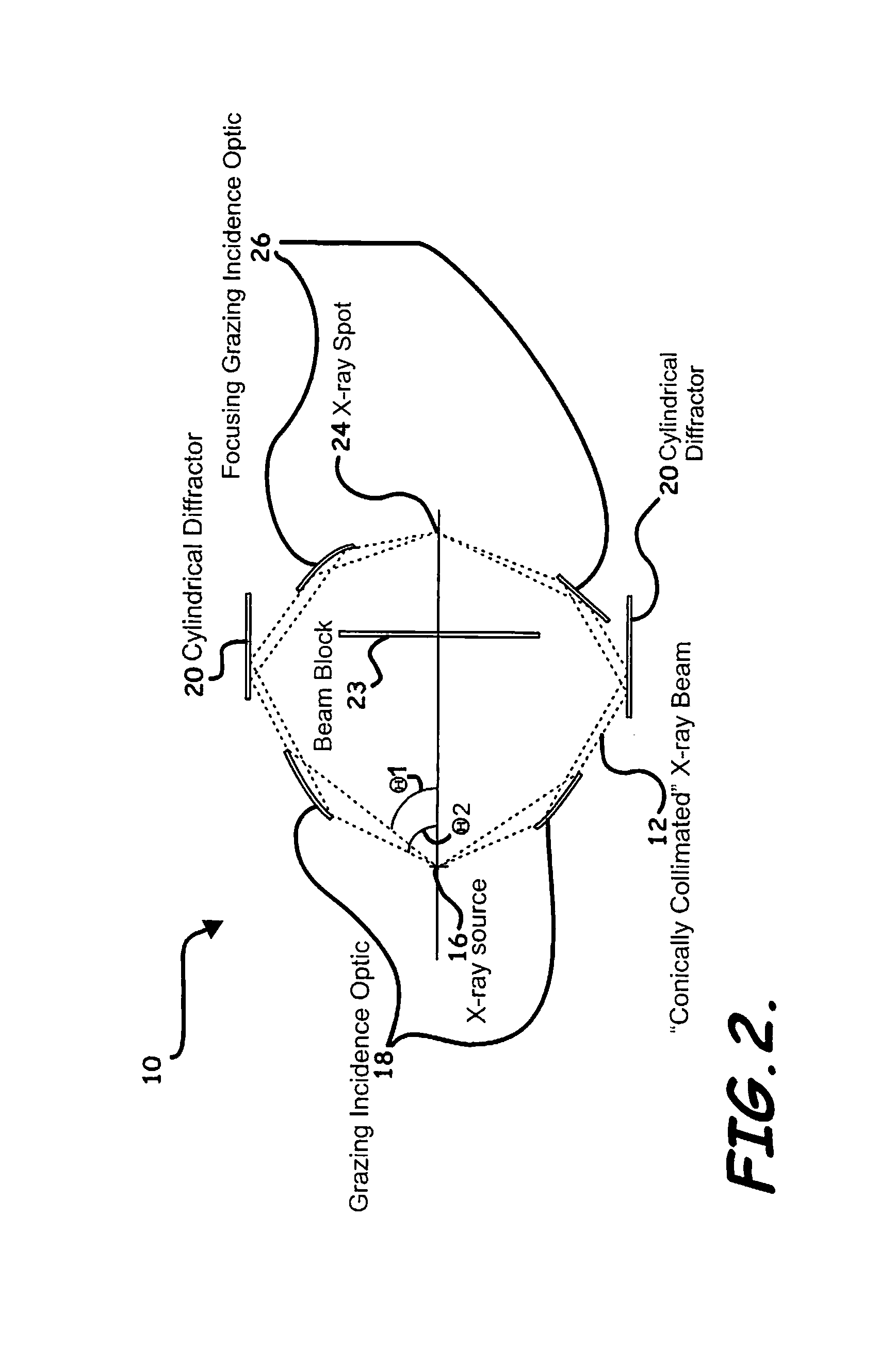
[0009]The concept of a “conically parallel” beam may be better understood by reference to FIG. 1, where diverging rays are shown to be generated from a small spot x-ray source and reflec...

Problems solved by technology

Pollution control requirements have pushed allowable levels of contaminants such as Sulfur in fuels (coal, diesel, gasoline, etc.) to such low levels that they are becoming difficult to measure.
One previous technique, X-ray Fluorescence Spectroscopy (XRF) is capable of measuring levels as low as 10 ppm in Diesel fuel but lower levels become difficult.
This difficulty is the result of getting sufficient x-ray flux from the primary excitation beam onto the target, getting the desirable energy of x-rays onto the target, and getting sufficient characteristic x-rays out of the target and into a detector.
Most current systems are inefficient at this because they collect a very small portion of the emitted x-rays.
Unfortunately, many WDS systems suffer from low count rates because the diffractor collects a small solid angle of the emitted x-rays.
It is sometimes possible to move the diffractor closer to collect a larger solid angle but this causes poor resolution.

Method used


Image

  • Apparatus employing conically parallel beam of X-rays
  • Apparatus employing conically parallel beam of X-rays
  • Apparatus employing conically parallel beam of X-rays

Examples


Embodiment Construction

[0016]The present invention will now be described more fully hereinafter with reference to the accompanying drawings, in which preferred embodiments of the invention are shown. Unless otherwise defined, technical and scientific terms used herein have the same meaning as commonly understood by one of ordinary skill in the art to which this invention pertains. Although methods and materials similar or equivalent to those described herein can be used in the practice or testing of the present invention, suitable methods and materials are described below. Any publications, patent applications, patents, and other references mentioned herein are incorporated by reference in their entirety. In case of conflict, the present specification, including any definitions, will control. In addition, the materials, methods and examples given are illustrative in nature only and not intended to be limiting. Accordingly, this invention may be embodied in many different forms and should not be construed ...


PUM


Abstract

An apparatus directing x-rays along a predetermined axis includes an x-ray optic having one or more nested x-ray reflector rings positioned relative to a source generating broad spectrum x-rays so that generated x-rays moving away from the predetermined axis are collected by the reflector incident at or close to a Bragg angle to thereby reflect the collected x-rays into a conically parallel beam. A first diffractor is positioned relative to the x-ray optic to receive incident thereon the conically parallel beam, the first diffractor selected from a truncated cone and a cylinder and diffracting the conically parallel beam toward the predetermined axis. A second diffractor is positioned relative to the first diffractor and having a geometry effective to receive incident thereon and redirect the conically parallel beam along the predetermined axis as a collimated beam of substantially parallel x-rays.

Description

RELATED APPLICATION[0001]This application is a continuation-in-part of and claims priority from nonprovisional application Ser. No. 11 / 279,676, which was filed on Apr. 13, 2006 now abandoned, and also from provisional application Ser. No. 60 / 779,303, which was filed on Mar. 3, 2006, both of which applications are incorporated herein by reference in their entirety.FIELD OF THE INVENTION[0002]This invention relates to an X-ray apparatus and, more specifically, to an X-ray apparatus employing a conically parallel beam of X-raysBACKGROUND OF THE INVENTION[0003]Pollution control requirements have pushed allowable levels of contaminants such as Sulfur in fuels (coal, diesel, gasoline, etc.) to such low levels that they are becoming difficult to measure. One previous technique, X-ray Fluorescence Spectroscopy (XRF) is capable of measuring levels as low as 10 ppm in Diesel fuel but lower levels become difficult. This difficulty is the result of getting sufficient x-ray flux from the primary...

Claims


Application Information

Patent Timeline
IPC IPC(8): G21K1/06
CPCG21K1/06G21K2201/067G21K2201/064G21K2201/062
Inventor O'HARA, DAVID
Owner OHARA DAVID
Learn More