
System and method for controlling constant power dissipation

a technology of constant power dissipation and memory cells, applied in the field of memory cells, can solve the problems of memory cells dissipating different levels of power, memory cells not heating uniformly, and insufficient power dissipation

Inactive Publication Date: 2008-08-12
INFINEON TECH AG +1
View PDF2 Cites 10 Cited by
  • Summary
  • Abstract
  • Description
  • Claims
  • Application Information

AI Technical Summary

Benefits of technology

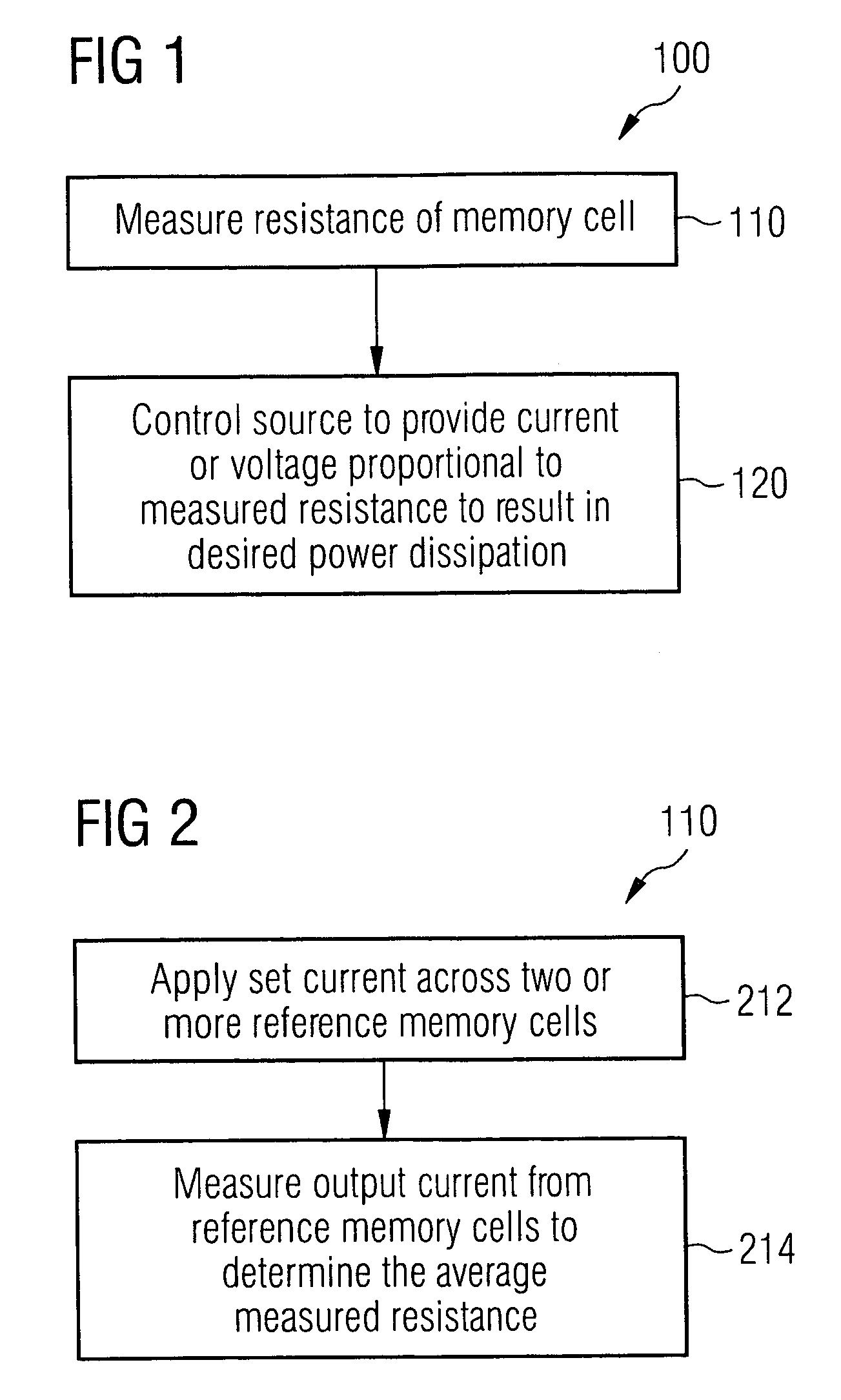
[0007]The present invention provides a system and method for controlling the constant power dissipation of a memory cell based upon the measured resistance of the memory cell or collection or memory cells representative of the particular memory cell. By controlling the memory cell's power dissipation as a function of the memory cell's resistance, a desired power dissipation, and accordingly, a desired heating temperature, can be achieved. In this way, memory cells having different resistances can be made to operate at substantially the same power dissipation levels and heating temperatures.

Problems solved by technology

A disadvantage with the conventional approach is the non-uniform heating of memory cells.
Thus, the application of a uniform writing current to cells with the aforementioned differences will result in those memory cells dissipating different levels of power, and accordingly, operating at different cell temperatures.
The condition of memory cells operating at different temperatures is disadvantageous, in that some memory cells may be dissipate insufficient power and achieve an insufficient level of heating for proper programming, while other memory cells may dissipate excessive power and reach very high temperatures that could damage the memory cell or reduce its normal operational lifetime.

Method used


Image

  • System and method for controlling constant power dissipation
  • System and method for controlling constant power dissipation
  • System and method for controlling constant power dissipation

Examples


first embodiment

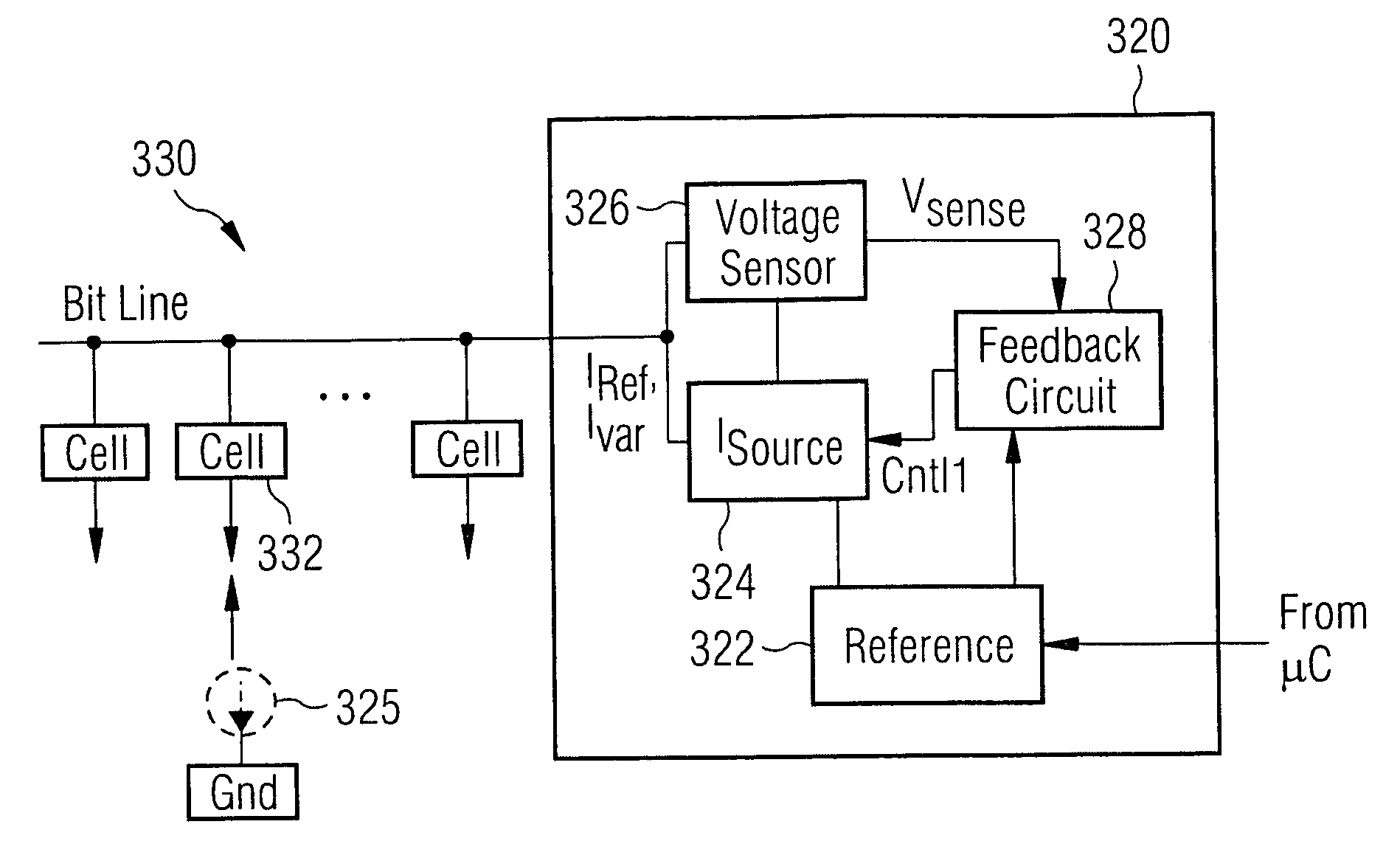
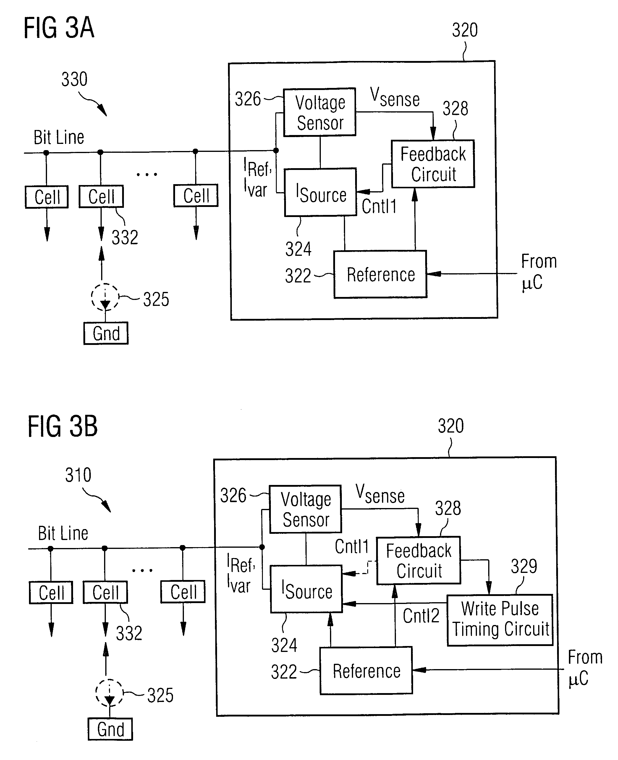
[0026]FIG. 3A illustrates a system configured to control heating of a memory cell in accordance with the present invention. The heating control system 320 includes a reference source 322, a current source 324, an optional current meter 325, a voltage sensor 326 and a feedback circuit 328. In an embodiment of the invention, the feedback circuit 328 comprises a temperature sensor for detecting, e.g., the temperature of the chip and / or the temperature of the cell. In a particular embodiment, the system 320 is monolithically-formed in an integrated circuit (Si, SiGe, GaAs, Silicon-on-Insulator (SOI), and the like) with an array of MRAM or other memory cells where application of a constant amount of write power is beneficial (e.g., phase-change memory).

[0027]Current source 324 includes inputs for receiving a current level control signal Cntl1, and an output coupled to memory cell 332 for providing a variable level of current thereto, the current being supplied along the bit line of the m...

second embodiment

[0032]FIG. 3B illustrates a system configured to control heating of a memory cell in accordance with the present invention. In addition to the above-described features, the heating control system 320 further includes a timing circuit 329 operable to generate a variable pulse width control signal Cntl2. Control signal Cntl2 controls the duration over which the current source 324 applies current to the memory cell 332, and accordingly, the total amount of heat energy supplied to the memory cell. In an exemplary embodiment, the heating duration of the memory cell is in the range of approximately 2 ns to approximately 100 ns.

[0033]When configured in this embodiment, the timing circuit operates to extend the pulse width, or increase the duration of the current applied to the memory cell when the sensed voltage is below the aforementioned expected voltage. Under the reverse conditions, the timing circuit decreases the pulse width and duration of the current source when the sensed voltage ...


PUM


Abstract

A method for controlling the constant power dissipation of a memory cell includes initially measuring the resistance of the memory cell, and subsequently controlling a source to apply a variable level of current or voltage to the memory cell. The variable level of the applied current or voltage is determined in proportion to the measured resistance of the memory cell so as to result in a predefined level of power dissipation within the memory cell, said dissipated power operable to heat the memory cell.

Description

TECHNICAL FIELD[0001]The present invention relates to memory cells, and more particularly to systems and methods for controlling a constant power dissipation in memory cells.BACKGROUND[0002]As known in the art, magneto random access memory (MRAM) cells are more easily programmed when heated due to the storage or data layer's low coercivity at elevated temperatures. Accordingly, the storage layer can be programmed to the desired parallel / low resistive state or anti-parallel / high resistive state with less writing current than would be required if the memory cell were programmed without heating.[0003]Memory cell programming is typically accomplished by supplying a write current to the memory cell that is to be programmed, the memory cell dissipating a level of power as a result of conducting the supplied writing current, and the dissipated power generating heat. The level of power dissipated is dependent upon the magnitude of the writing current supplied and the resistance of the memor...

Claims


Application Information

Patent Timeline
Patent Type & Authority Patents(United States)
IPC IPC(8): G11C5/14
CPCG11C5/14G11C11/2297G11C13/0038G11C11/16
Inventor KLOSTERMANN, ULRICHGOGL, DIETMAR
Owner INFINEON TECH AG
Learn More