Slit lamp microscope

a technology of slit lamp and microscope, which is applied in the field of slit lamp microscope, can solve the problems of increasing the physical burden on both examiner and subject, deteriorating accuracy, and increasing inspection time, so as to improve the parallelism of slit, improve the accuracy of slit, and facilitate the change of slit width

Active Publication Date: 2008-08-12
KK TOPCON
View PDF8 Cites 3 Cited by
  • Summary
  • Abstract
  • Description
  • Claims
  • Application Information

AI Technical Summary

Benefits of technology

[0030]Another object of the present invention is to provide a slit lamp microscope allowing the slit width changing operation to be performed easily and capable of preventing spontaneous closing of the slit.
[0036]According to the present invention, there is provided the second urging means for urging the pair of holding members so as to press them against the shaft member, so that the holding members can rotate around the shaft member in a stable manner. This helps to achieve an improvement in the parallelism of the slit formed by the gap of the slit forming members held by the holding members, making it possible to generate high precision slit light.
[0037]Further, according to the present invention, there can be made the position of the urging means for urging the pair of holding members so as to cause the pair of slit forming members to move away from each other with an urging force weaker than that of the first urging means that urges the pair of slit forming members so as to bring them close to each other, the second urging means acts so as to cancel a part of the urging force of the first urging means. Thus, when rotating the pair of holding means to change the slit width, the requisite force for the operation of vertically moving the first engagement member of the engagement portion of the slit width changing means can be small, so that the examiner can change the slit width easily.
[0038]Furthermore, due to the canceling of a part of the urging force of the first urging means by the second urging means, the force applied to the pair of holding members becomes more stable, whereby it is possible to prevent spontaneous closing of the slit.

Problems solved by technology

First, since the slope of the lower portions of the side surfaces of the inter-casing distance varying member 87 is gentle, slippage is likely to occur between the side surfaces and the bearings 101L and 101R, and, due to the urging force of the urging means, it can happen that slippage actually occurs to cause the slit 54 to close spontaneously. This leads to a deterioration in the accuracy in the slit width, which is of importance in observation by using the slit lamp microscope. Further, when such spontaneous closing occurs, additional time is required to re-adjust the slit width, resulting in an increase in inspection time, which leads to an increase in the physical burden on both the examiner and subject. In particular, for the examiner, who has to examine a number of patients a day, such spontaneous closing of the slit is nothing but a bother.
Accordingly, a great force is needed when adjusting the slit, which is disadvantageous in terms of operability.
It might be possible to effect design change so as to make the slope of the side surfaces of the inter-casing distance varying member 87 steeper; it should be noted, however, that the conventional slope configuration has been adopted for such a long time that many examiners are quite used to the relationship between its operating amount and slit width change; thus, such design change is not so desirable from the viewpoint of operability.
Another problem in the prior art is related to the parallelism of the slit.
In the prior-art technique, however, there are cases in which it is rather difficult to form the slit parallel.
It is to be assumed that the difficulty is due partly to the heat of the light source and partly to the accuracy at the time of production.
When a slit lamp microscope is used for a long period of time, the interior of the apparatus may attain high temperature due to the heat from the light source.
That will make it impossible for the casings 100L and 100R to rotate uniformly to the right and left, resulting in formation of a distorted slit which is not parallel.

Method used


Image

  • Slit lamp microscope
  • Slit lamp microscope
  • Slit lamp microscope

Examples


Embodiment Construction

[0051]A slit lamp microscope according to an embodiment of the present invention will be described in detail with reference to the drawings.

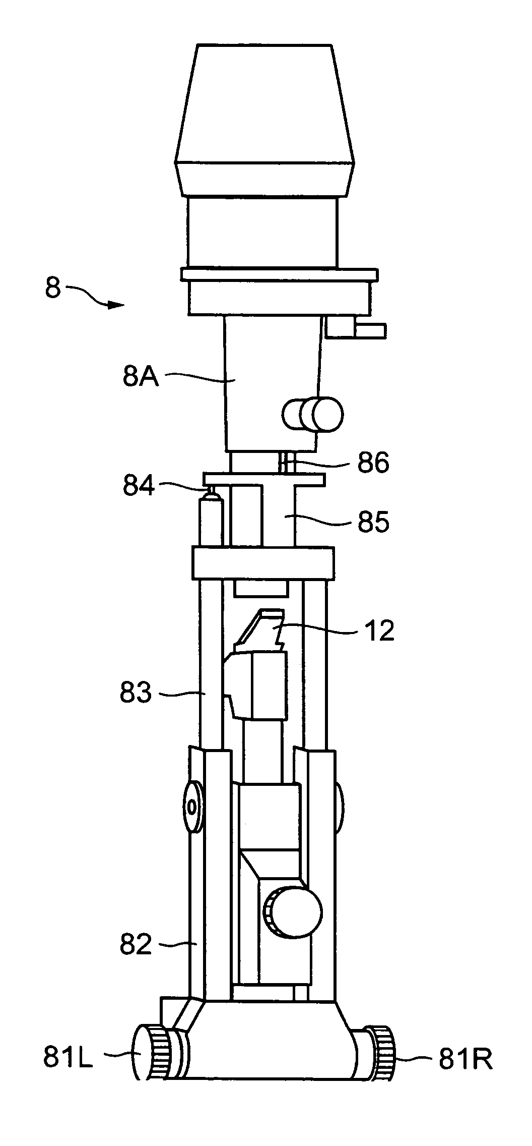
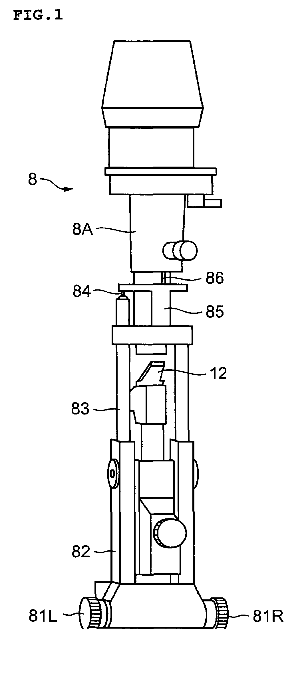
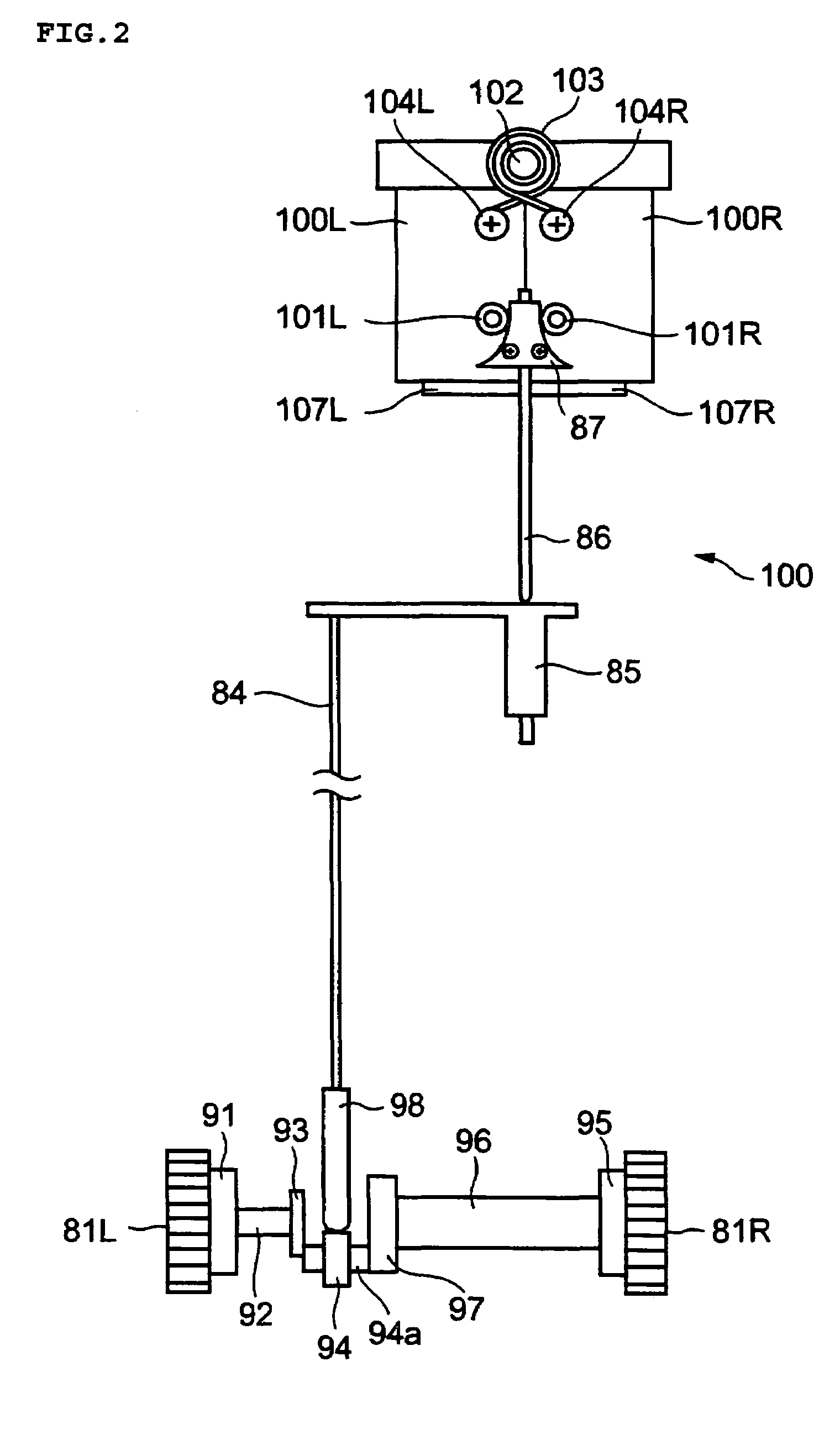
[0052]The slit lamp microscope of this embodiment has an external construction and an optical configuration (in particular, an observation system 6 and an illumination system 8) similar to those of the above-described conventional slit lamp microscope (see FIGS. 8 and 9). Further, this slit lamp microscope has a slit forming means substantially the same as that in the prior art (see FIGS. 10 and 11). In the following, the components that are the same as those of the conventional slit lamp microscope are indicated by the same reference numerals.

[0053]Here, the term slit forming means refers to a structure including a pair of slit blades constituting the pair of slit forming members as used in the present invention and a slit width changing means changing the slit width by changing the distance between the pair of slit blades. The term slit width ...


PUM


Abstract

Disclosed is a slit lamp microscope capable of forming a slit superior in terms of parallelism. The slit lamp microscope includes casings (100L and 100R) to the bottoms surfaces of which slit blades (107L) and (107R) are fixed and which are connected together so as to be rotatable around shaft members (102), and an inter-casing distance varying member (87) adapted to change the distance between the casings (100L and 100R) in correspondence with vertical movement of an ascent / descent shaft (86). Coil-like portions of torsion springs (103) are wound around the shaft members (102) to which the casings (100L and 100R) are connected. The torsion springs (103) urge the casings (100L and 100R) so as to bring the slit blades (107L and 107R) close to each other. Further, the casings (100L and 100R) are equipped with U-shaped springs (106) urging protrusions (100L′ and 100R′) thereof so as to press them against the shaft members (102).

Description

BACKGROUND OF THE INVENTION[0001]1. Field of the Invention[0002]The present invention relates to a slit lamp microscope for use in a field of ophthalmology, and more specifically to a slit lamp microscope with a special contrivance in its portion related to the formation of a slit.[0003]2. Description of the Related Art[0004]A slit lamp microscope has been used as a kind of microscope for use in the field of ophthalmology. A slit lamp microscope, which makes it possible to observe various lesion parts of an eye to be examined through a contrivance in illumination, is used for day-to-day diagnosis by eye doctors.[0005]JP2003-299619 A (claims, paragraphs [0019] to [0026] in the specification, and FIGS. 1 and 2) discloses an example of the construction of a conventional slit lamp microscope. The slit lamp microscope as disclosed in the above-mentioned publication includes: an illumination system which applies slit light to the eye to be examined (hereinafter simply referred to as “the ...

Claims


Application Information

Patent Timeline
Patent Type & Authority Patents(United States)
IPC IPC(8): A61B3/10A61B3/12A61B3/135
CPCA61B3/135A61B3/12
Inventor TAKEDA, TAKANORI
Owner KK TOPCON
Why Eureka
Try Eureka