
Methods and systems for mixed-mode physical synthesis in electronic design automation

a technology of electronic design automation and mixed-mode physical synthesis, applied in the field of electronic design automation, can solve the problems of consuming substantial computational resources and eda processes that are extremely complex, and achieve the effect of reducing the number of interconnections

Active Publication Date: 2008-08-05
SYNOPSYS INC
View PDF13 Cites 7 Cited by
  • Summary
  • Abstract
  • Description
  • Claims
  • Application Information

AI Technical Summary

Benefits of technology

The present invention is about methods and systems for electronic design automation. It involves converting RTL code into objects and clustering them into manageable numbers. The clusters are then floorplanned to reduce interconnections between them. The placement of objects within the clusters takes into account placement-based wire load models. The invention also includes a bottoms-up procedure where area and size constraints of clustered objects are considered. The technical effects of the invention include improved efficiency and accuracy in electronic design automation.

Problems solved by technology

EDA processes tend to be extremely complex and consume substantial computational resources.

Method used


Image

  • Methods and systems for mixed-mode physical synthesis in electronic design automation
  • Methods and systems for mixed-mode physical synthesis in electronic design automation
  • Methods and systems for mixed-mode physical synthesis in electronic design automation

Examples


example implementation

B. Example Implementation of Floorplanning and Placement During Physical Synthesis

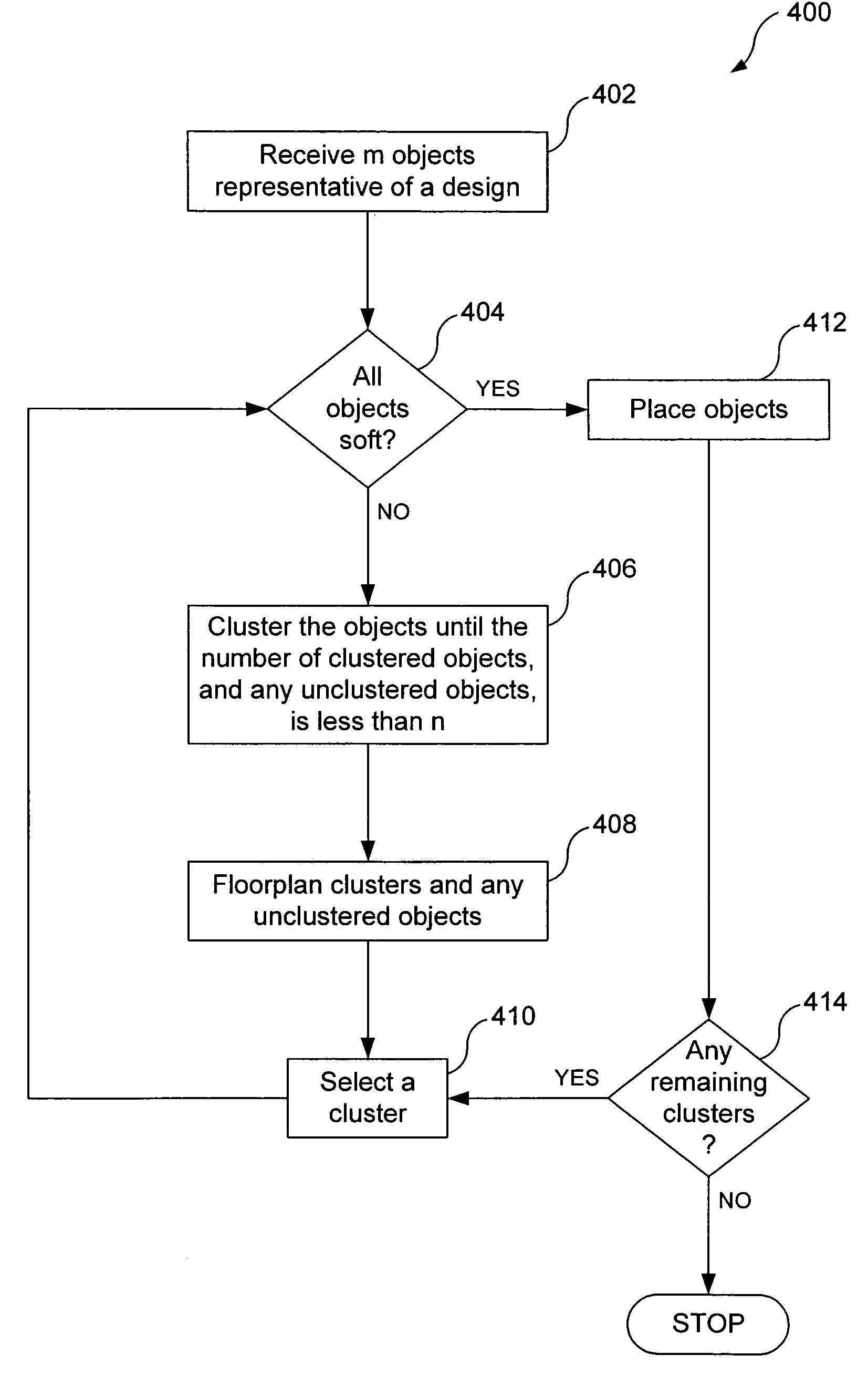
[0088]FIG. 4 is a flowchart of an example process 400 for clustering, floorplanning, and placing objects, including logic objects, during front-end physical synthesis.

[0089]FIG. 3 is an example illustration of m objects 300 representative of RTL 208, where m is an integer. In a typical design layout, there are between hundreds and thousands of m objects 300. Optionally, the m objects 300, or a portion of the m objects 300, include logic objects that include detailed physical information, as described above.

[0090]The example process 400 is described below with respect to the m objects 300. The example process 400 is not, however, limited to the m objects 300. Based on the description herein, one skilled in the relevant art(s) will understand that the process 400 can be implemented with other objects.

[0091]In order to place the m objects 300 in a design layout, the m objects 300 are analyzed. If there ex...


PUM


Abstract

Methods and systems for electronic design automation includes clustering objects into more manageable numbers of objects. Clustering is optionally performed to reduce or minimize interconnections between clusters. Clustering optionally includes multi-level clustering. The clusters, and any unclustered objects, are floorplanned. Floorplanning positions the clusters so as to reduce or minimize the length of interconnections between the clusters. Objects within the clusters are then placed within the area assigned to the corresponding clusters. Placement optionally utilizes placement-based wire load models to accurately predict timing issues. A bottoms-up procedure is optionally performed during clustering and / or floorplanning, whereby area and / or size constraints of clustered objects are taken into account.

Description

CROSS-REFERENCE TO RELATED APPLICATIONS[0001]The present invention claims the benefit of U.S. Provisional Application No. 60 / 575,420, filed Jun. 1, 2004, which is hereby incorporated by reference in its entirety.BACKGROUND OF THE INVENTION[0002]1. Field of the Invention[0003]The invention relates to electronic design automation and, more particularly, to mixed-mode physical synthesis.[0004]2. Related Art[0005]Integrated circuits are designed using computer-based hardware description languages (“HDLs”), which are analogous to computer program source code. Electronic design automation (“EDA”) tools are used to reduce the HDL code to actual integrated circuit designs. The integrated circuit designs can then be fabricated into integrated circuits. Reduction of HDL code to a circuit design is analogous to the reduction (i.e., compiling) of computer program source code to machine language code. EDA processes can “reduce” hundreds or thousands of lines of HDL code to millions of transistor...

Claims


Application Information

Patent Timeline
Patent Type & Authority Patents(United States)
IPC IPC(8): G06F17/50G06F9/45
CPCG06F17/5072G06F17/5045G06F30/30G06F30/392
Inventor SHANG, ZHONG-QING
Owner SYNOPSYS INC
Learn More