
Motion estimation engine with parallel interpolation and search hardware

a motion estimation and hardware technology, applied in the field of motion estimation, can solve the problems of large increase in the memory bandwidth used for motion estimation or motion compensation, inability to use a low-cost hardware decoder, and high computational intensity of the sub-pixel interpolation process in accordance with h.264, and achieve the effect of fast encoding and small area

Active Publication Date: 2008-08-05
AVAGO TECH INT SALES PTE LTD
View PDF10 Cites 5 Cited by
  • Summary
  • Abstract
  • Description
  • Claims
  • Application Information

AI Technical Summary

Benefits of technology

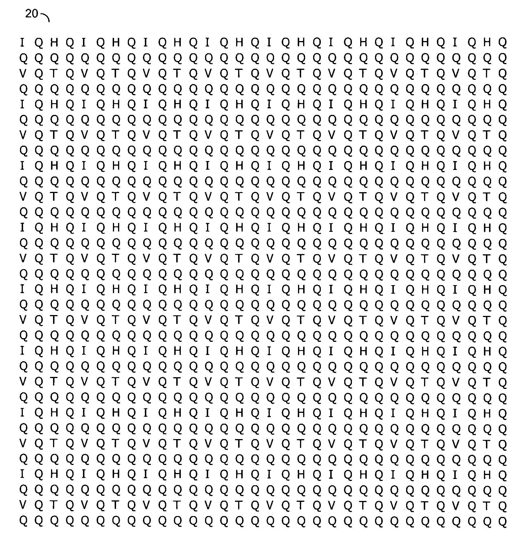
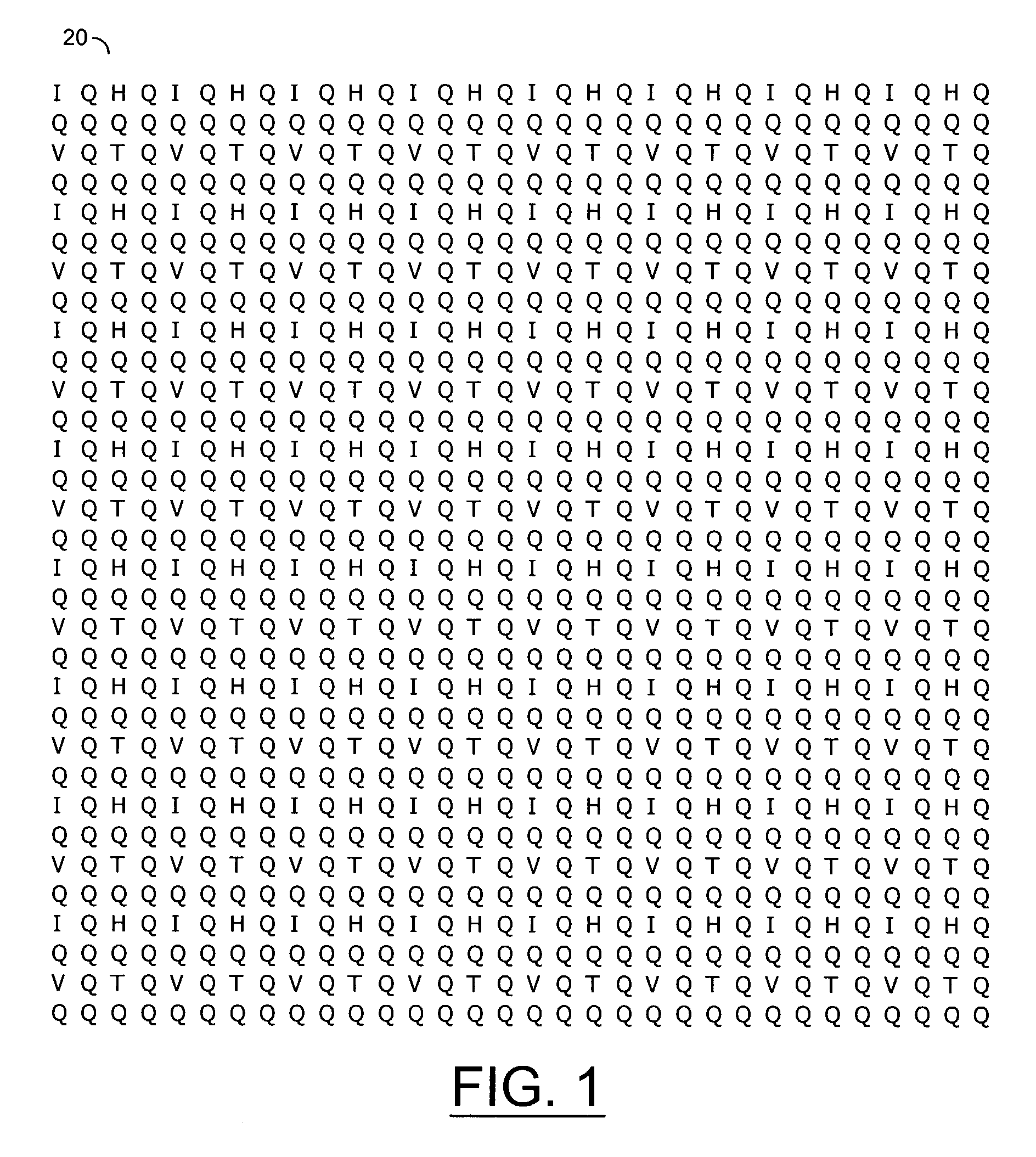
The present invention is about a method for estimating motion in videos. The method involves generating a first interpolated block with a resolution of one-fourth of a pixel, based on a reference block of a reference frame. This block is then used to create a motion vector, which is used to generate a second interpolated block with a resolution of one-eighth of a pixel. This method has several advantages, including being small in size, operating at low clock speed, and providing fast encoding and decoding. It also allows for quick software processing and closed loop encoding.

Problems solved by technology

The sub-pixel interpolation process in accordance with H.264 can be very computationally intensive.
However, the first technique is not appropriate for a low-cost hardware decoder.
The drawbacks of the first technique include (i) using a large amount of memory since each reference frame uses 16 times as much memory as is otherwise needed and (ii) a memory bandwidth used for motion estimation or motion compensation is greatly increased.
For long sub-pixel filters, such as those used in H.264, the second technique is very inefficient.
Computing 64 sub-pixel positions is much more complicated and time consuming then computing the error between the interpolated pixels and other pixels.
Therefore, the second technique can be slow and much of the time the “error” hardware will be idle, waiting for the “interpolation” hardware to complete.

Method used


Image

  • Motion estimation engine with parallel interpolation and search hardware
  • Motion estimation engine with parallel interpolation and search hardware
  • Motion estimation engine with parallel interpolation and search hardware

Examples


Embodiment Construction

[0022]The present invention concerns multiple methods that may efficiently perform sub-pixel motion estimation. The approaches may be used independently or together. A first approach generally uses a simple interpolation process, such as using only bi-linear interpolation for motion estimation. A more complex, long-filter method may be used for motion compensation. Another approach generally performs an integer pixel search substantially simultaneously with an interpolation pipelines to a sub-pixel search. Variations on the approaches may also be implemented.

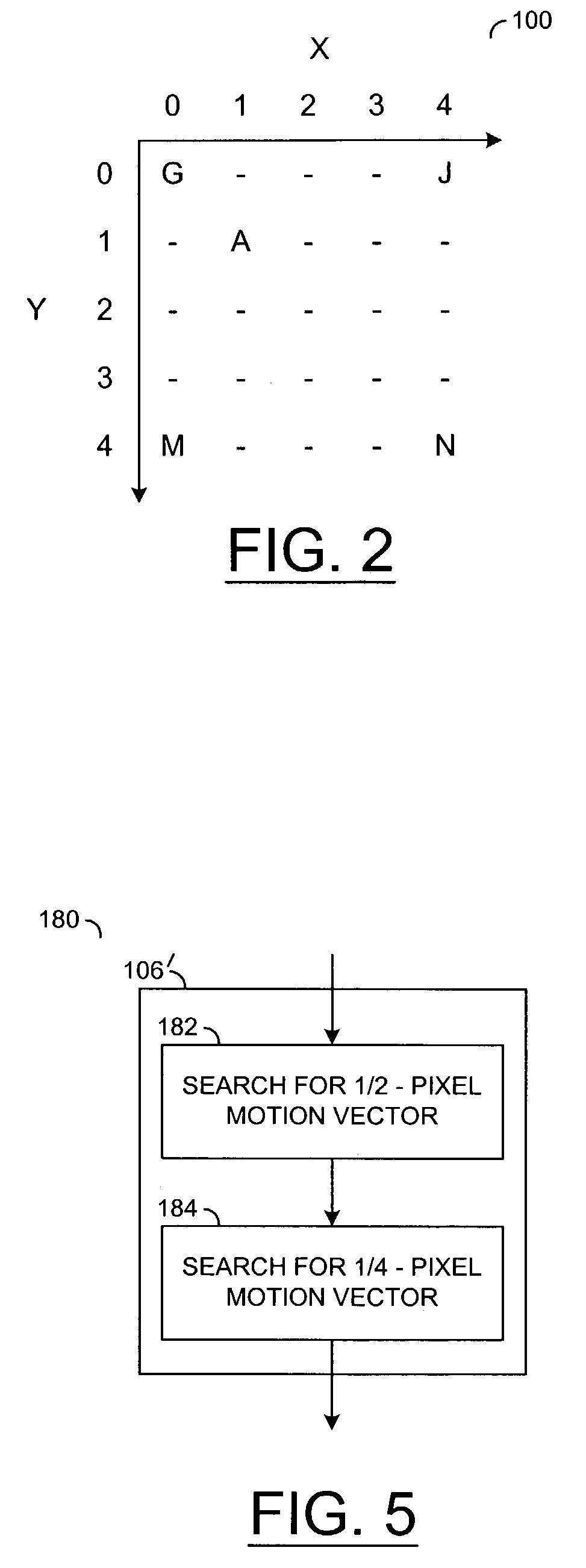
[0023]Referring to FIG. 2, an illustration of several example pixels in a frame 100 of a video signal is shown. The pixels may illustrate an interpolation in accordance with an embodiment of the present invention. Image information from four neighboring integer pixels (e.g., G, J, M and N) may be interpolated to generate an interpolated pixel or sample (e.g., A). The interpolated pixel A may be at a horizontal distance (e.g., X)...


PUM


Abstract

A method for motion estimating. The method generally includes the steps of (A) generating a first interpolated block having a sub-pixel resolution in response to a first interpolation process operating on a reference block of a reference frame of a video signal having an integer pixel resolution, (B) generating a motion vector in response to the first interpolated block and a current block of a current frame of the video signal having the integer pixel resolution and (C) generating a second interpolated block having the sub-pixel resolution in response to a second interpolation process operating on the reference block.

Description

CROSS REFERENCE TO RELATED APPLICATIONS[0001]The present application may relate to co-pending application Ser. No. 10 / 324,487 filed Dec. 20, 2002, which is hereby incorporated by reference in its entirety.FIELD OF THE INVENTION[0002]The present invention relates to motion estimation generally and, more particularly, to a motion estimation engine with parallel interpolation and search hardware.BACKGROUND OF THE INVENTION[0003]Compression of digital video data is performed for many applications, including but not limited to transmission over bandwidth constrained channels, such as satellite broadcasts, and storage on optical media. In order to achieve very efficient compression, complex, computationally intensive processes are used for encoding (compressing) and decoding (decompressing) video. For example, even though MPEG-2 (Motion Picture Expert Group) is known as a very efficient method for compressing video, a new, more efficient standard (i.e., H.264) is being developed.[0004]Par...

Claims


Application Information

Patent Timeline
Patent Type & Authority Patents(United States)
IPC IPC(8): H04N7/18H04N7/32G06T7/20G09G3/20H04N5/14H04N7/12H04N7/26
CPCG06T7/2013H04N5/145H04N19/57H04N19/533H04N19/523H04N19/43G06T2207/10016G06T7/223
Inventor LINZER, ELLIOT N.LEUNG, HO-MINGHAN, SOO-CHUL
Owner AVAGO TECH INT SALES PTE LTD
Learn More