
Well logging method for determining formation characteristics using pulsed neutron capture measurements

a well logging and formation characteristic technology, applied in the field of formation logging, can solve the problems of poor repeatability, poor likelihood that some of these are actual sigmas of problems, and noisy noise, and achieve the effect of repeatable smooth behavior and poor repeatability

Active Publication Date: 2008-08-05
SCHLUMBERGER TECH CORP
View PDF9 Cites 35 Cited by
  • Summary
  • Abstract
  • Description
  • Claims
  • Application Information

AI Technical Summary

Benefits of technology

[0014]One of the features of the present invention involves use of regularization in an inversion to obtain optimized exponential components of a forward model. An advantage of regularization is that it allows for fitting of many sigma (capture cross section) values, substantially more than the number of windows or gates, while maintaining a repeatable smooth behavior. Without regularization one would have two choices, neither giving reliable results: (1) one can use many sigma values and obtain a very noisy, poorly repeatable result; or (2) one can use only a few values of sigma with poor likelihood that some of these are actual sigmas of the problem. If few or none of the values chosen are close to a true values, the fit will be poor and generate unphysical amplitudes at other sigma values.

Problems solved by technology

Without regularization one would have two choices, neither giving reliable results: (1) one can use many sigma values and obtain a very noisy, poorly repeatable result; or (2) one can use only a few values of sigma with poor likelihood that some of these are actual sigmas of the problem.
If few or none of the values chosen are close to a true values, the fit will be poor and generate unphysical amplitudes at other sigma values.

Method used


Image

  • Well logging method for determining formation characteristics using pulsed neutron capture measurements
  • Well logging method for determining formation characteristics using pulsed neutron capture measurements
  • Well logging method for determining formation characteristics using pulsed neutron capture measurements

Examples


Embodiment Construction

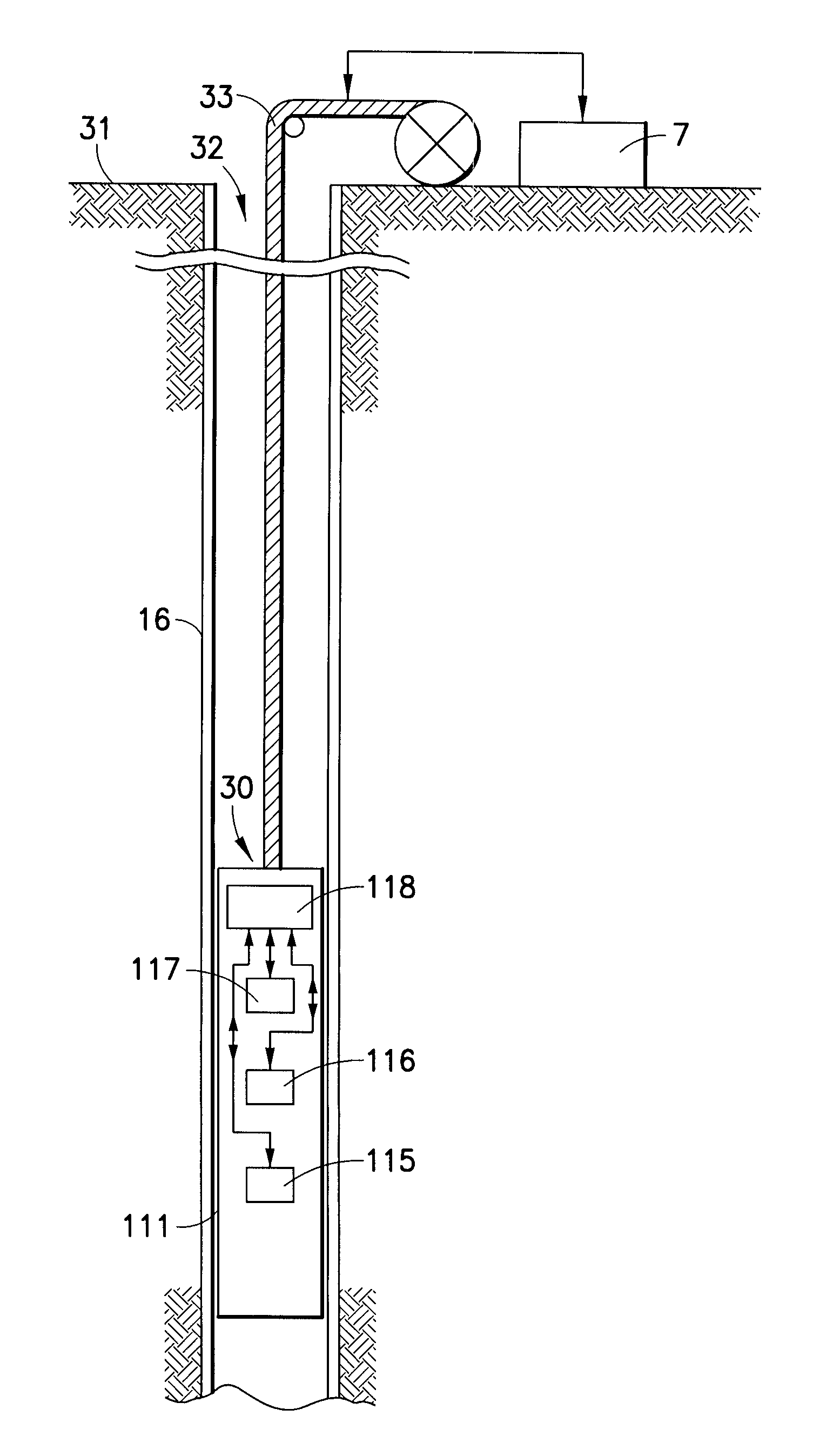
[0025]Referring to FIG. 1, there is shown an apparatus for investigating subsurface formations 31 traversed by a borehole 32, which can be used in practicing embodiments of the invention. The borehole 32 is typically, but not necessarily filled with a drilling fluid or mud which contains finely divided solids in suspension, and mudcake 16 is shown on the walls of the borehole.

[0026]A pulsed neutron capture investigating apparatus or logging device 30 is suspended in the borehole 32 on an armored cable 33, the length of which substantially determines the relative depth of the device 30. As is known in the art, this type of device can also operate in a well having casing or tubing. The length of cable 33 is controlled by suitable means at the surface such as a drum and winch mechanism (not shown). The depth of the tool within the well bore can be measured by encoders in an associated sheave wheel, the double-headed arrow representing communication of the depth level information to the...


PUM


Abstract

A method for determining thermal capture cross-sections of formations surrounding an earth borehole, including the following steps: providing a logging device that is moveable through the borehole; transmitting, from the logging device, bursts of neutrons into the formations; detecting, at the logging device, resultant gamma ray counts, and deriving a measurement spectrum from the gamma ray counts; deriving a forward model comprising a combination of model exponential components having respective model decay times and model amplitudes; deriving an error function that depends on comparison between the forward model and the measurement spectrum; and determining, by regularized inversion, optimized exponential components of the model that substantially minimize the error function; the optimized exponential components being indicative of the thermal capture cross-sections of the formations.

Description

FIELD OF THE INVENTION[0001]This invention relates to logging of formations surrounding an earth borehole and, more particularly, to techniques for determining characteristics of the formations using pulsed neutron capture measurements and extraction therefrom of thermal capture cross-sections.BACKGROUND OF THE INVENTION[0002]Thermal capture cross-section logging, or thermal neutron die-away logging, has been in use for decades to monitor the saturation history of a reservoir in cased holes. Macroscopic thermal capture cross-section, or Σ, is sensitive to the presence of strong thermal absorbers. Chlorine is one such absorber, and chlorine is commonly present in formation water, while not present in any hydrocarbons. Thus, Σ-logging can often be used to obtain water saturation. It is performed by irradiating the formation with pulsed neutron beams and by monitoring the returning gamma radiation, which results from the capture of thermal neutrons by highly-absorbing isotopes present ...

Claims


Application Information

Patent Timeline
Patent Type & Authority Patents(United States)
IPC IPC(8): G01V5/10
CPCG01V5/125
Inventor FLAUM, CHARLESMORRIS, JR., CHARLES FRANKLIN
Owner SCHLUMBERGER TECH CORP
Learn More