
Nozzle interconnect

a technology of interconnection and nozzle, which is applied in the direction of liquid transfer devices, liquid handling, packaging goods types, etc., can solve the problems of shutting down any business, complex and technical fields, and dispensing gasoline, and achieve the effect of convenient use and preventing untimely flow

Active Publication Date: 2008-08-05
HUSKY CORP
View PDF5 Cites 12 Cited by
  • Summary
  • Abstract
  • Description
  • Claims
  • Application Information

AI Technical Summary

Benefits of technology

"This patent describes a safety feature for fuel dispensing nozzles that prevents unauthorized or untimely dispensing of fuel. The safety feature is achieved through an interconnect that allows for proper operation of the nozzle only when it is properly located within the vehicle's fill pipe. The interconnect includes a link that is mounted for longitudinal shifting within the nozzle and is biased forwardly to prevent the nozzle from being turned on when not in use. This safety feature ensures that fuel cannot be dispensed unless the nozzle is properly fitted into the vehicle's fill pipe."

Problems solved by technology

The dispensing of gasoline or other fuels from fuel dispensing nozzles, as anyone knows who is familiar with the technology of this art, is a very complex and technically sophisticated field, evidenced by the numerous minutely shiftable and moving parts that are integrated into the structure of such a nozzle, to keep it working effectively.
If any one of the foregoing cannot be achieved, CARB and the related governmental regulatory agencies will ban the use of any nozzle, and shut down any business, if not an entire industry, if they do not think that their regulations are being closely followed, and the limits achieved.
It may be that the vehicle owner, while self-serving in delivery of gasoline into their vehicle, may think that the tank is filled, or that the dispenser has ceased the delivery of gasoline, and therefore withdraw the nozzle from the fill pipe, which unless the dispenser is actually shut off, could lead towards further splashing of gasoline onto the car, onto the surrounding ground, or even onto the person, because of a misjudgment.

Method used


Image

  • Nozzle interconnect
  • Nozzle interconnect
  • Nozzle interconnect

Examples


Embodiment Construction

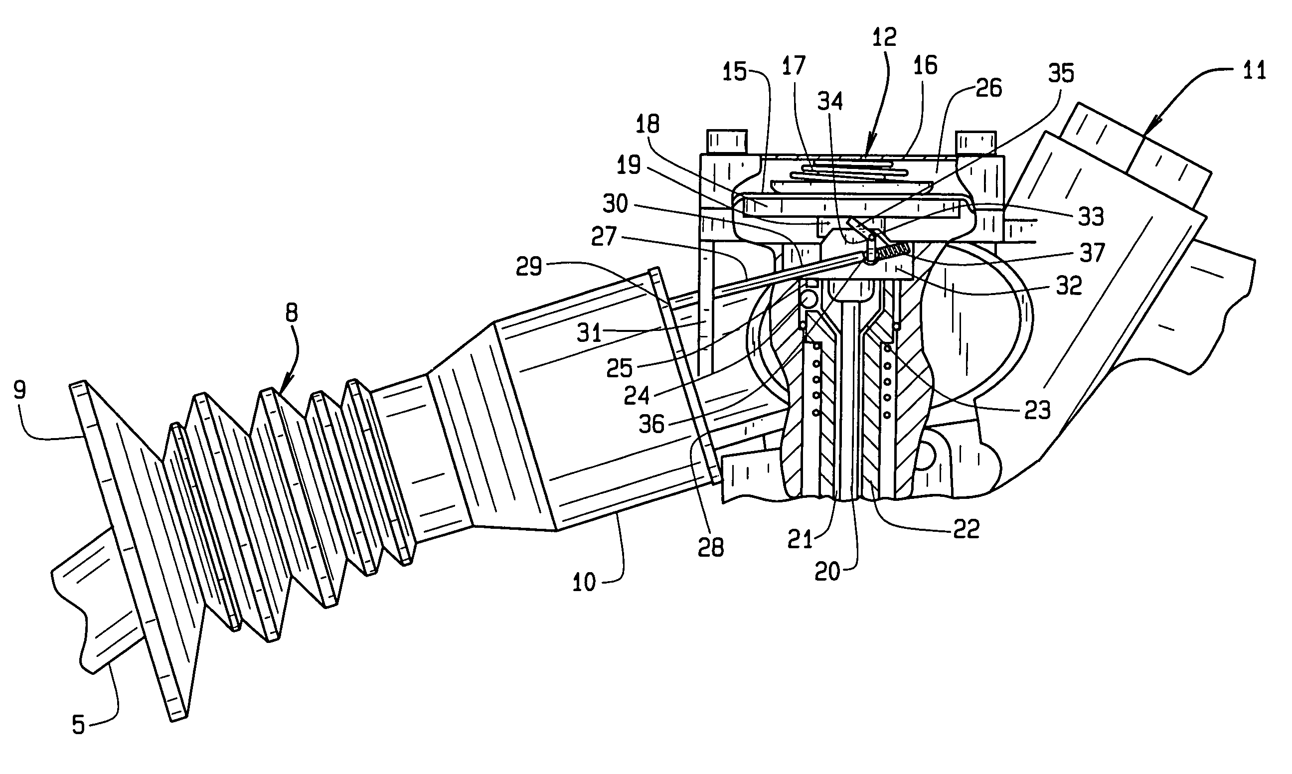
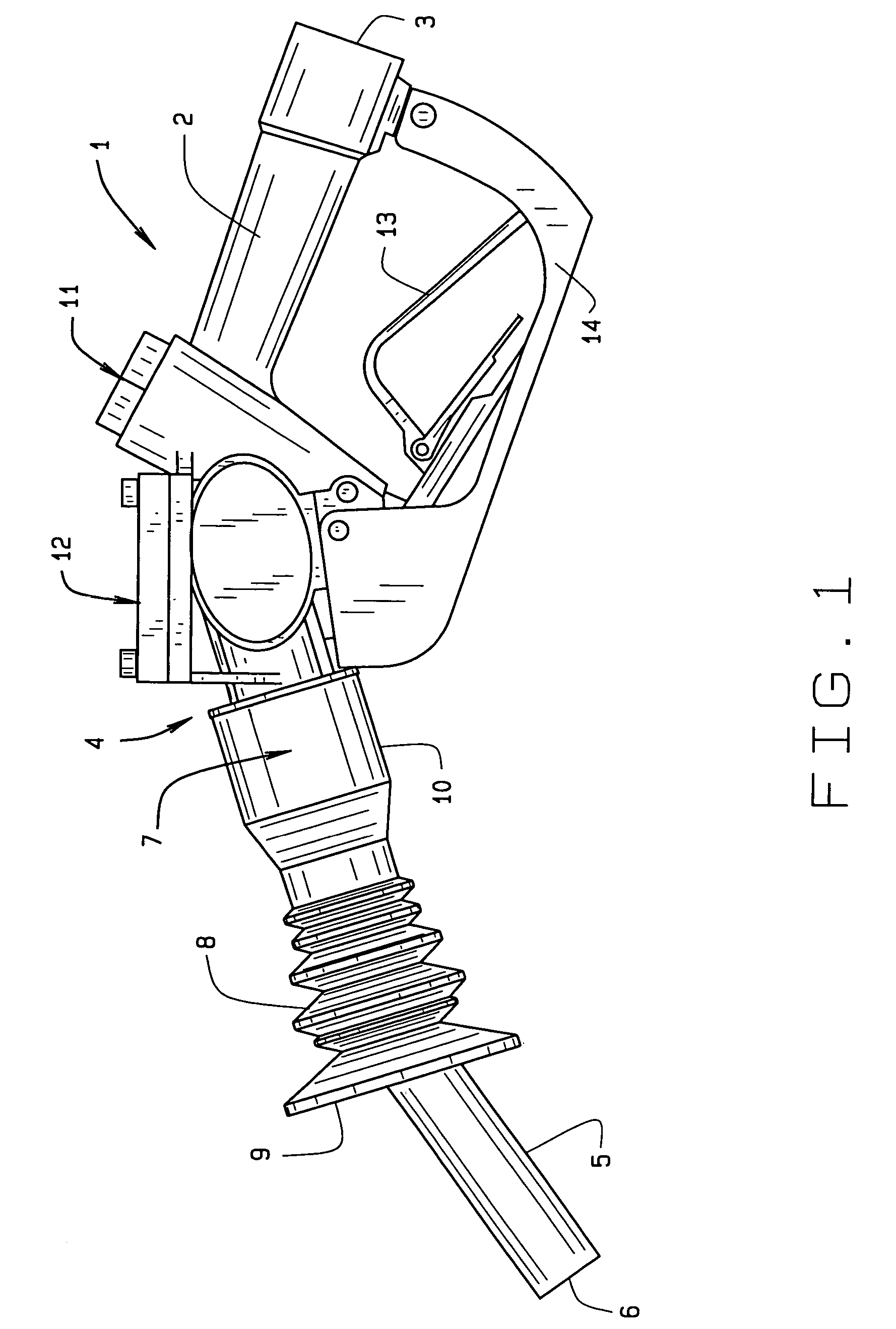
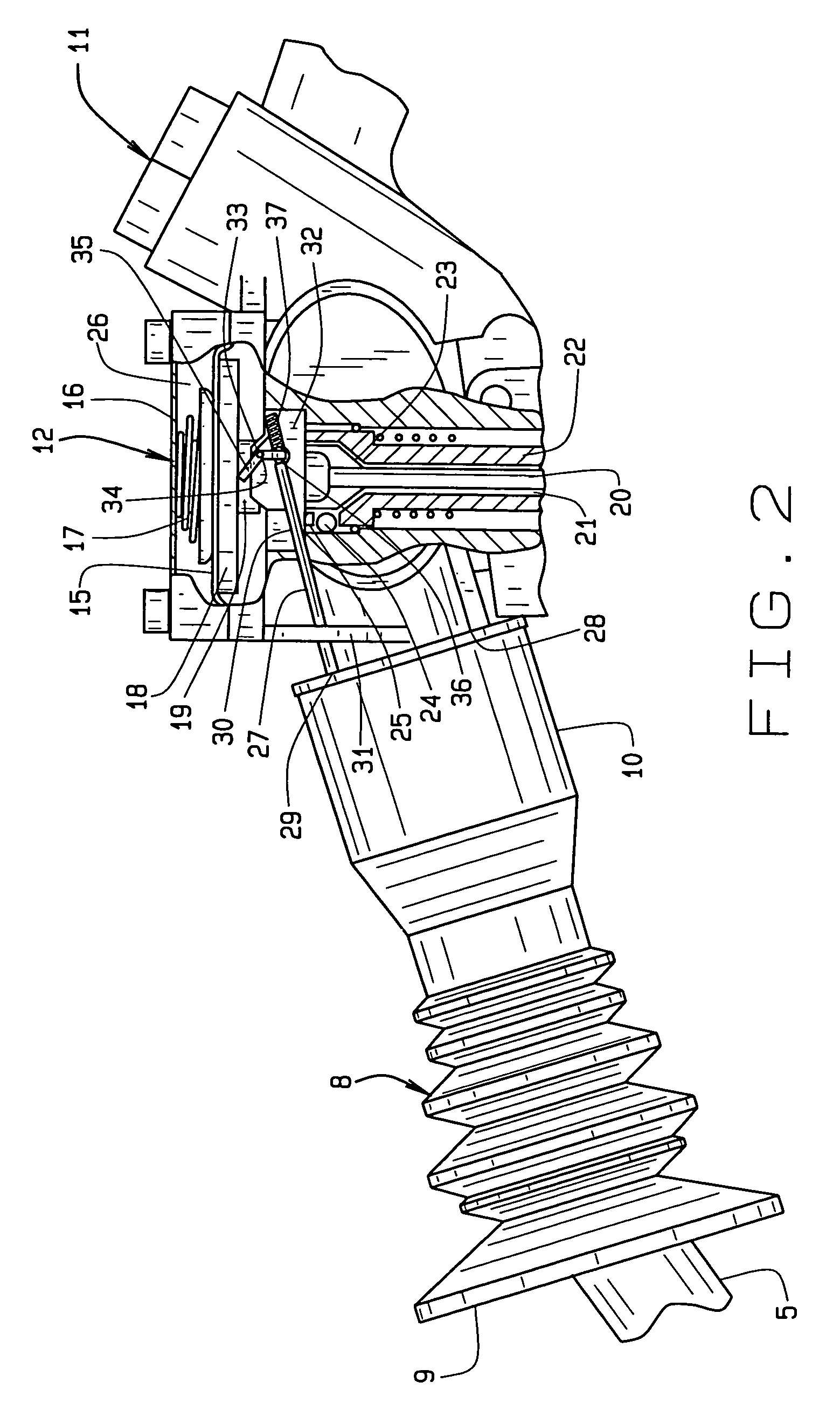
[0028]In referring to the drawings, and in particular FIG. 1, a gasoline dispensing nozzle 1 is readily disclosed. It includes a body 2 having an inlet 3 to which the fuel hose (not shown) is connected. The nozzle also has an outlet 4 communicating with a spout 5 assembly. The spout assembly 5 has a mouth 6 that is insertable into the inlet of a container, such as the fill pipe of the fuel tank into which the liquid is to be dispensed. Disposed within the nozzle body 2, and between its inlet and outlet, is a venturi valve, in the region of 7, internally of the nozzle, as known in the art. With this particular nozzle, there is also included a bellows like member 8, having a splashguard located at its forward region 9, and the bellows includes a mounting section, as at 10, that fits onto the upper region of the spout, which in this particular instance, is capable of longitudinal or axial movement upon the spout, or at least some segment of the member 10 is capable of axial movement, a...


PUM

PropertyMeasurementUnit
angleaaaaaaaaaa
timeaaaaaaaaaa
pressuresaaaaaaaaaa

Abstract

An interconnect for a fuel dispensing nozzle which provides for sustained shut off of a nozzle when its spout is not inserted into the fill pipe of a fuel tank. When the spout inserts within the fill pipe its bellows or splashguard is forced rearwardly, for urging an interconnecting rod to move rearwardly, against the bias of a spring, to force a pivotal link to disengage from the automatic shut-off diaphragm, to allow it to function normally. But when the nozzle is removed from the fuel tank, the pivotal link contacts against the diaphragm structure, of the automatic shut-off, and prevents the nozzle from dispensing or delivering any fuel from the dispenser.

Description

CROSS REFERENCE TO RELATED APPLICATION[0001]This non-provisional application claims priority to the provisional application for patent Ser. No. 60 / 678,583 which was filed on May 6, 2005.BACKGROUND OF THE INVENTION[0002]This invention relates generally to a fuel dispensing nozzle, and more specifically relates to a nozzle incorporating a safety feature that assures that when a fuel dispensing nozzle is removed from the fill pipe of a vehicle, the nozzle will shut off, and prevent any further fuel dispensing, until such time as it is reintroduced into another vehicle fill pipe, in preparation for further fuel dispensing.[0003]The dispensing of gasoline or other fuels from fuel dispensing nozzles, as anyone knows who is familiar with the technology of this art, is a very complex and technically sophisticated field, evidenced by the numerous minutely shiftable and moving parts that are integrated into the structure of such a nozzle, to keep it working effectively. The nozzles, and their...

Claims


Application Information

Patent Timeline
Patent Type & Authority Patents(United States)
IPC IPC(8): B65B1/30B67D7/54
CPCB67D7/54B67D2007/545
Inventor MITCHELL, THOMAS O.
Owner HUSKY CORP
Learn More