Diagonal matrix delay

a delay and diagramming technology, applied in the field of integrated circuits, can solve problems such as spikes or other electrical disturbances on outputs

Inactive Publication Date: 2008-07-29
MARVELL ISRAEL MISL
View PDF16 Cites 2 Cited by
  • Summary
  • Abstract
  • Description
  • Claims
  • Application Information

AI Technical Summary

Problems solved by technology

In addition, if the changes are not made with a “zero” transition, a spike or other electrical disturbance can be created on the output 107.

Method used


Image

  • Diagonal matrix delay
  • Diagonal matrix delay
  • Diagonal matrix delay

Examples


Embodiment Construction

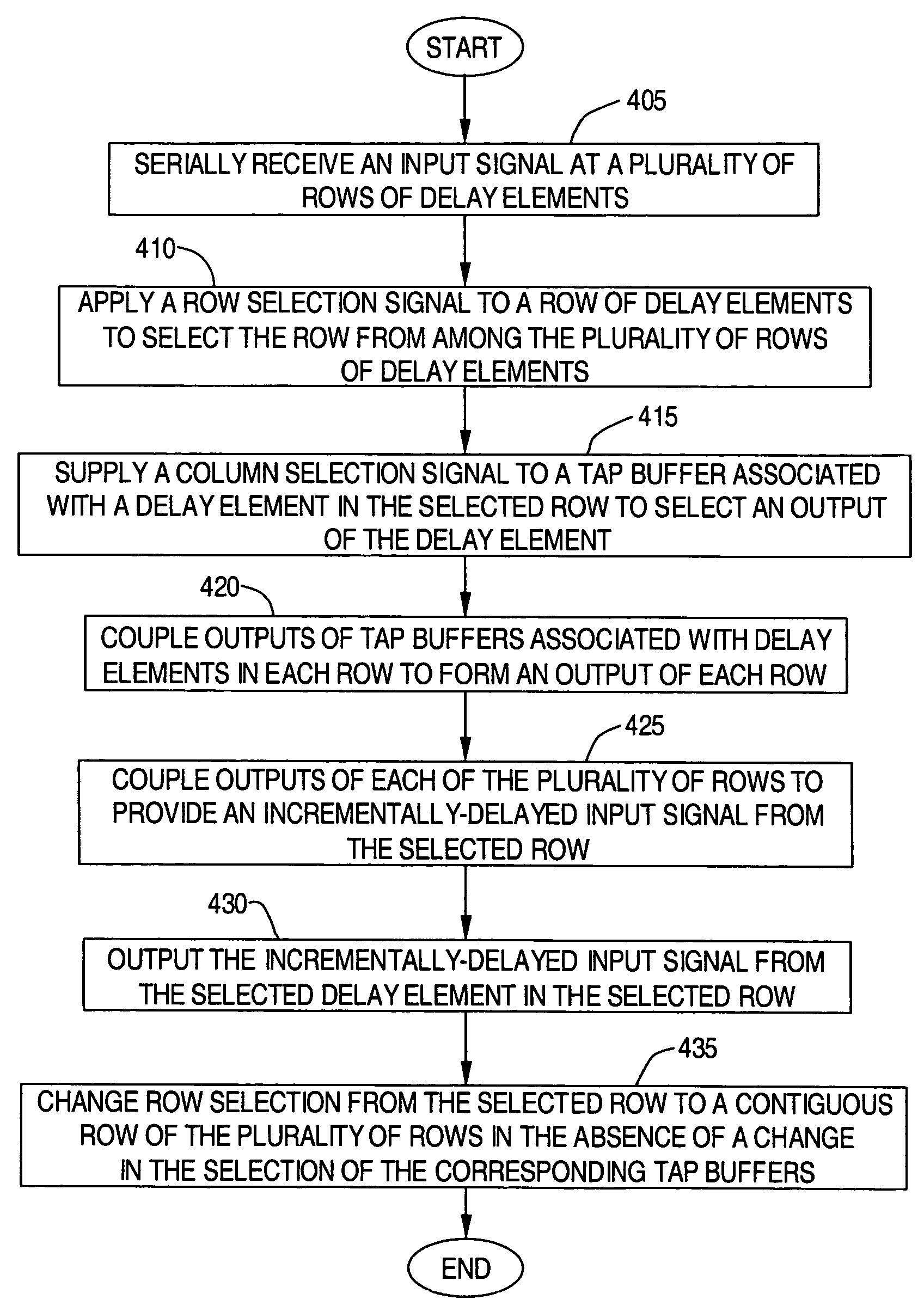
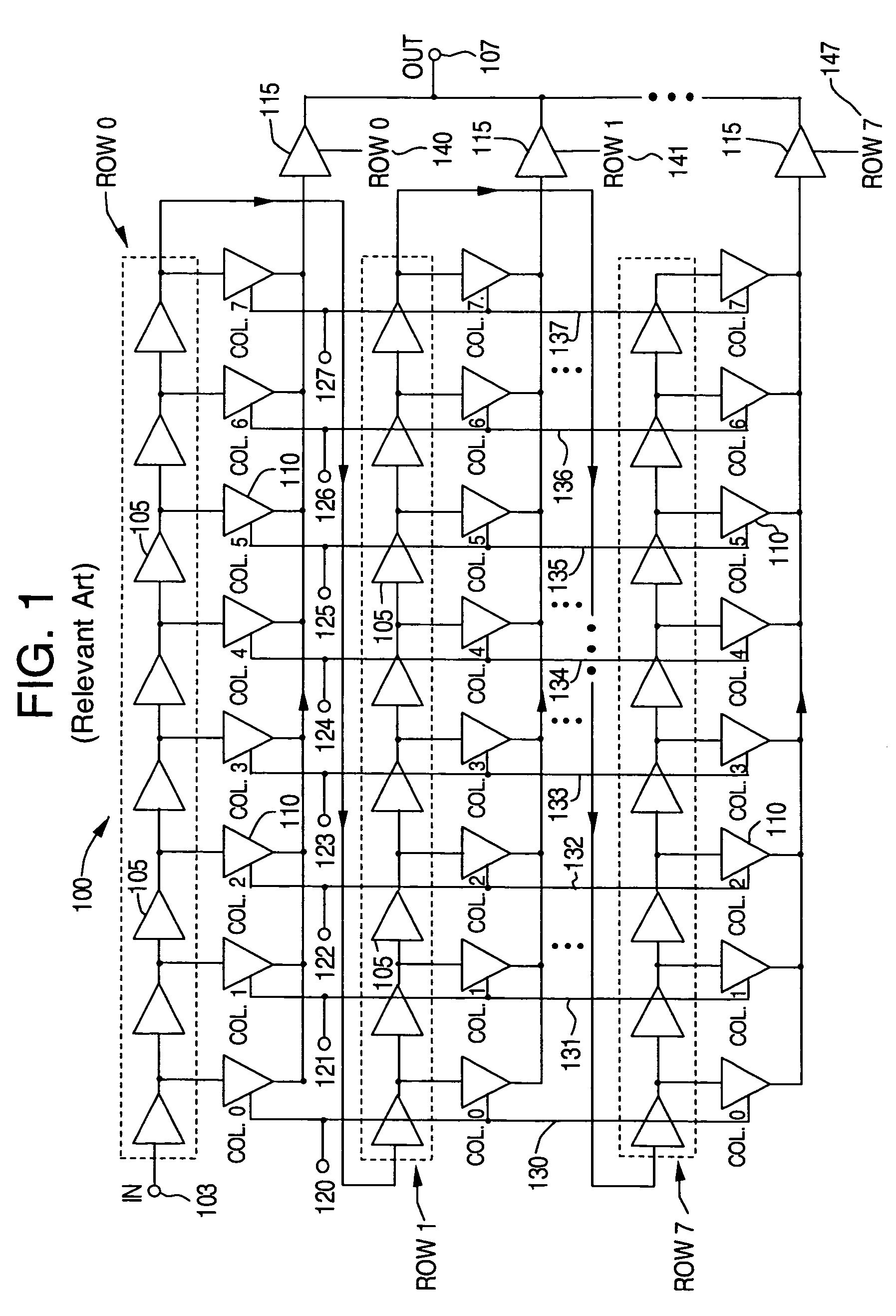
[0029]Exemplary embodiments of the present invention are directed to a diagonal matrix delay system and method for delaying an input signal and providing an output signal. According exemplary embodiments, a programmable matrix delay is comprised of rows of delay elements. Each delay element within a row can be selected by an associated tri-state buffer. The tri-state buffers are formed in columns across the rows. To move within a row to increase or decrease the delay of the input signal by, for example, a single delay element at a time, a column counter can be incremented or decremented by single units. However, to move between contiguous rows (e.g., to move from the delay element associated with the last column of a row to the delay element associated with the first column of the next row, or to move from the delay element associated with the first column of a row to the delay element associated with the last column of the previous row), only a row counter need be incremented or de...


PUM


Abstract

A method of delaying an input signal comprises serially receiving the input signal at a plurality of rows of delay elements; applying a row selection signal to a row of delay elements to select the row from the plurality of rows; supplying a column selection signal to a tap buffer associated with a delay element in the selected row to select an output of the delay element; coupling outputs of tap buffers associated with delay elements in each row to form an output of each row; coupling outputs of each of the plurality of rows to provide an incrementally-delayed input signal from the selected row; outputting the incrementally-delayed input signal from the selected delay element in the selected row; and changing row selection from the selected row to a contiguous row of the plurality of rows in the absence of a change in the selection of the corresponding tap buffers.

Description

CROSS-REFERENCE TO RELATED APPLICATIONS[0001]The present application is a divisional of application Ser. No. 10 / 873,591 filed on Jun. 23, 2004 now U.S. Pat. No. 7,050,341, issued on May 23, 2006, which claims priority from U.S. Provisional Application Ser. No. 60 / 494,223, filed on Aug. 11, 2003, which are both hereby incorporated by reference in their entirety.FIELD OF THE INVENTION[0002]The present invention relates to integrated circuits. More particularly, the present invention relates to a diagonal matrix delay for delaying an input signal.BACKGROUND OF THE INVENTION[0003]FIG. 1 is a circuit diagram illustrating a conventional matrix delay 100 for delaying an input signal 103 and providing an output signal 107. For purposes of illustration, the delay matrix 100 can be comprised of eight rows (i.e., Row 0, Row 1, . . . , Row 7), with each row comprised of eight delay elements 105. The rows are arranged in serial communication with each other, with the delay elements 105 within ea...

Claims


Application Information

Patent Timeline
Patent Type & Authority Patents(United States)
IPC IPC(8): G11C7/00
CPCH03K5/15013H03K5/133H03K2005/00058
Inventor LABIN, TOMERMOSHE, DAVIDDINO, SHMUELGABAI, AMIR
Owner MARVELL ISRAEL MISL
Why Eureka
Try Eureka