
Modular sensor for damage detection, manufacturing method, and structural composite material

a module sensor and damage detection technology, applied in the direction of optical apparatus testing, optical radiation measurement, instruments, etc., can solve the problems of difficult damage detection with high degree of accuracy, inability to fully exploit the properties of composite materials (light and high strength), and heavy structure weight, etc., to achieve high visibility, high accuracy, and significant manageability

Active Publication Date: 2008-07-29
SUBARU CORP
View PDF10 Cites 37 Cited by
  • Summary
  • Abstract
  • Description
  • Claims
  • Application Information

AI Technical Summary

Benefits of technology

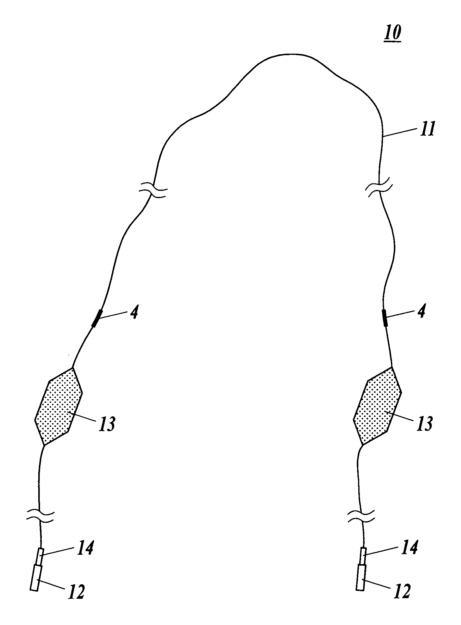
The present invention provides a modular sensor for damage detection that is embedded into a composite material, using an optical fiber with an FBG sensor and a connector. The modular sensor is easily visible and manageable, and can be embedded into the composite material at various positions. The optical fiber is covered by a tube that prevents breakage of the fiber at the end portion of the composite material. The modular sensor is reinforced by a reinforcing tube to prevent stress concentration to the optical fiber when connecting a connector. The invention also provides a manufacturing method for the modular sensor. These technical effects improve the detection and management of damage in composite materials.

Problems solved by technology

However, when this design method is adopted, weight of structure becomes heavy, and properties of the composite material (light and high in strength) cannot be taken in advantage fully.
However, since a place where polyimide film used in the technique is embedded is limited, it is difficult to detect damage with high degree of accuracy by embedding the polyimide film where damage occurs frequently.
However, since the thin diameter optical fiber is so thin that managing with the optical fiber is difficult and visibility is disturbed, a problem arose in that it is difficult to embed the optical fiber with thin diameter into the composite material.

Method used


Image

  • Modular sensor for damage detection, manufacturing method, and structural composite material
  • Modular sensor for damage detection, manufacturing method, and structural composite material
  • Modular sensor for damage detection, manufacturing method, and structural composite material

Examples


first embodiment

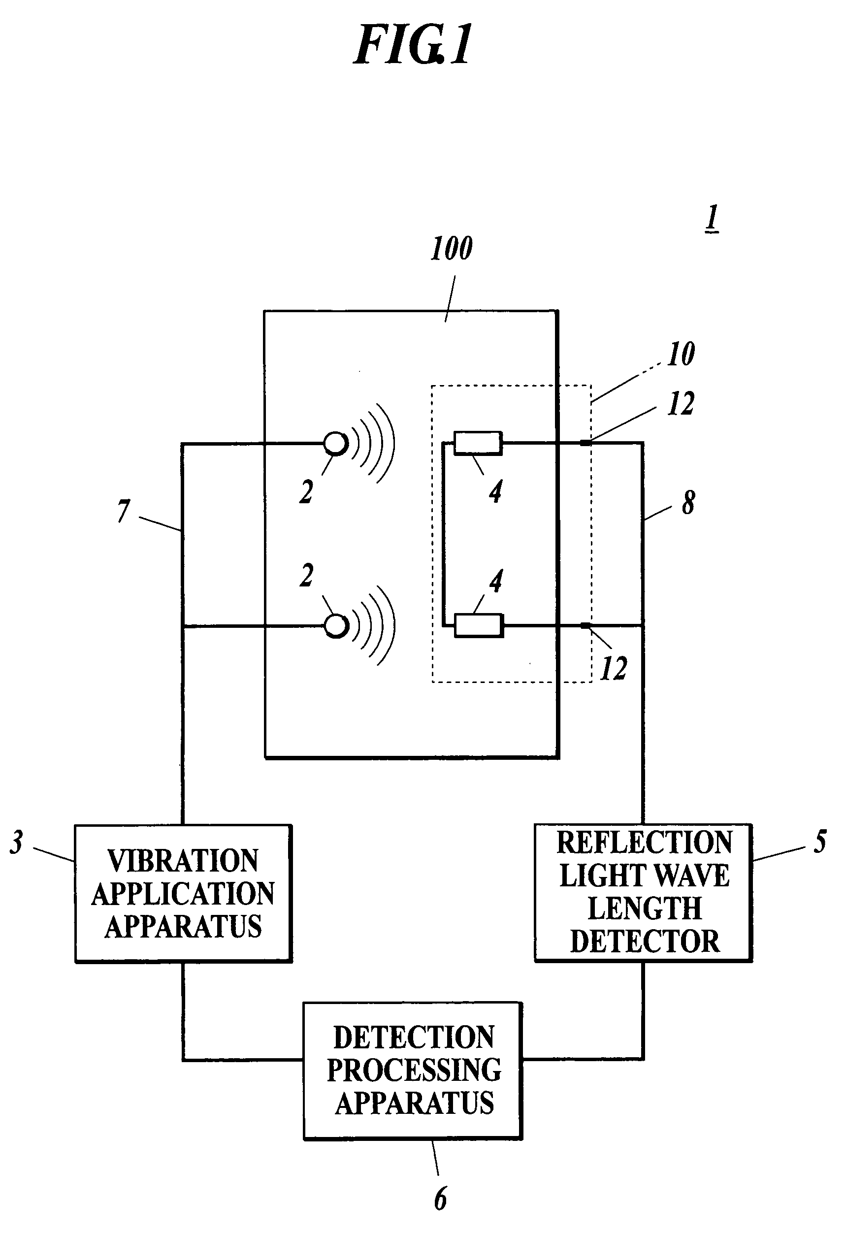
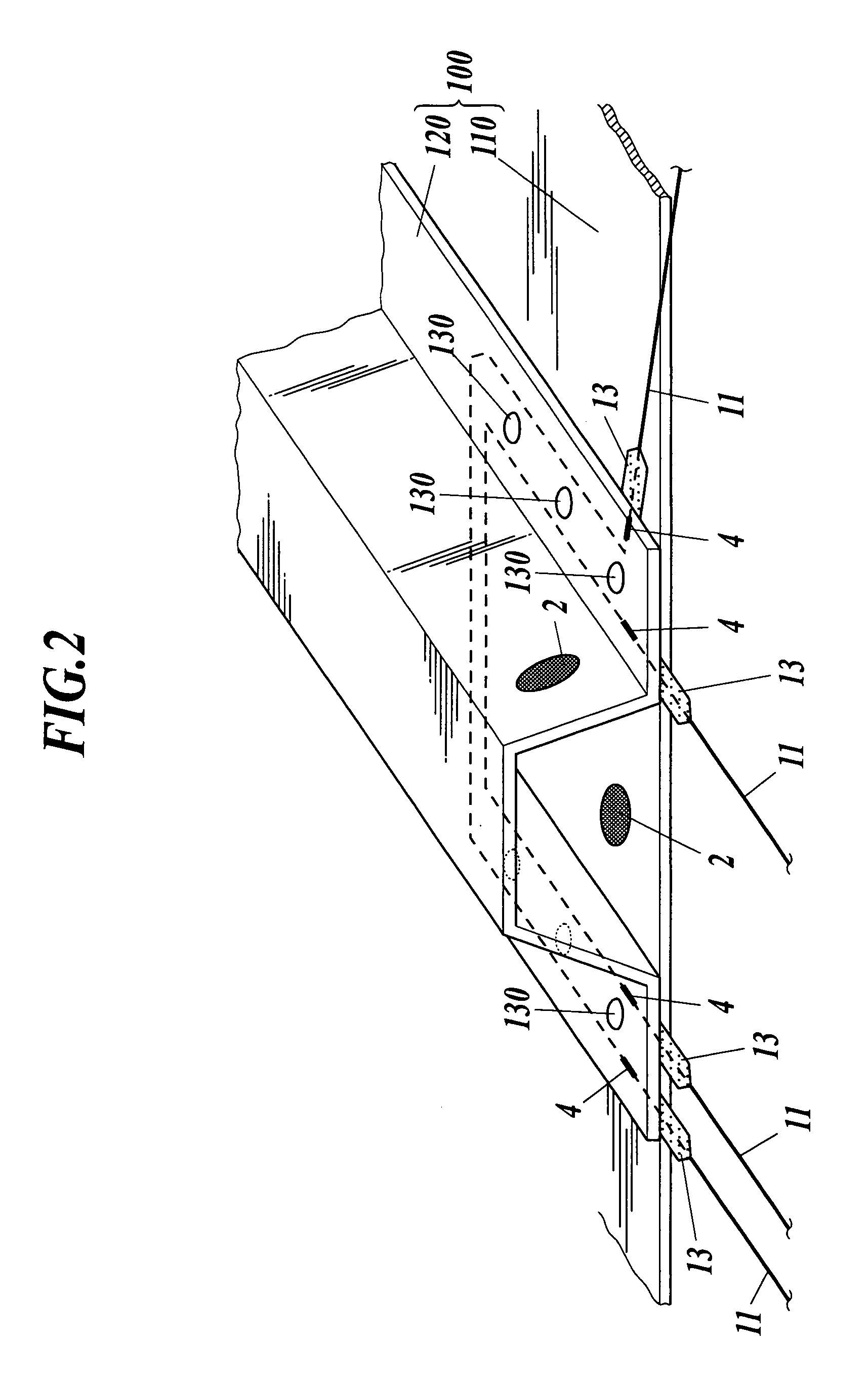
[0050]A first embodiment of the present invention will be described with reference to FIGS. 1 to 5. In this embodiment, described is an example where a modular sensor for damage detection is applied to a “damage detection system” that detects a damage of a composite material 100 for main wing of an aircraft, structured by bonding an outer plate 110, and a stringer 120 whose cross-section is a hat form, with a rivet 130 (refer to FIG. 2).

[0051]A structure of damage detection system 1 is described with reference to FIGS. 1 and 2.

[0052]As shown in FIGS. 1 and 2, the damage detection system 1 is structured with a plurality of piezo actuator 2 that are adhered to a planer surface of the composite material 100, a vibration application apparatus 3 that activates each piazo actuator by applying voltage, a plurality of FBG sensors 4 that are embedded into the composite material 100, a reflection light wave length detector 5 to detect change in characteristics of reflection light obtained fro...

second embodiment

[0084]Next, description of a second embodiment of the present invention will be described with reference to FIGS. 6 and 7.

[0085]A modular sensor for damage detection 10A of the present embodiment is a modification of the modular sensor for damage detection 10 of the first embodiment, in that polyimide tube 15 is used in place of the polyimide film 13, and other structures are practically the same with the first embodiment. Therefore, description will be given only for the modified structure, and numeric reference identical to that of the first embodiment is applied for the same structure with the first embodiment. In addition, since a damage detection system 1 embedded with the modular sensor for damage detection 10A of the present embodiment is practically the same with the damage detection system 1 of the first embodiment, description will be omitted.

[0086]As shown in FIG. 6, the modular sensor for damage detection 10A of the present embodiment is structured with a optical fiber 1...


PUM


Abstract

A modular sensor for damage detection with an optical fiber (FBG sensor) to detect a damage of a composite material, having a high level of visibility and manageability, and its manufacturing method is described. A structural composite material embedded with this modular sensor for damage detection is also described.

Description

BACKGROUND OF THE INVENTION[0001]1. Field of the Invention[0002]The present invention relates to a modular sensor for damage detection, manufacturing method, and structural composite material.[0003]2. Description of the Related Art[0004]Conventionally, fiber reinforced resin composite material (hereinafter called “composite material”) which is light and high in strength has been applied to various structural composite materials such as aircraft structures, space equipments, high-rise buildings, public infrastructures, high-speed vehicles, and the like. Since behavior of damage progress of the composite material is unclear compared to that of metal material, “safe life design” has been adopted in case of structuring structural composite material. However, when this design method is adopted, weight of structure becomes heavy, and properties of the composite material (light and high in strength) cannot be taken in advantage fully.[0005]Therefore, in these days, development in technique...

Claims


Application Information

Patent Timeline
Patent Type & Authority Patents(United States)
IPC IPC(8): G01J1/04G02B6/00G02B6/38
CPCG01D5/35303G01M11/086G01N21/1702G02B6/3644G01N2021/8472
Inventor OGISU, TOSHIMICHIKOJIMA, SEIJI
Owner SUBARU CORP
Learn More