Telescopic shaft for motor vehicle steering

a technology for steering shafts and motor vehicles, which is applied in crank shafts, couplings, transportation and packaging, etc., can solve the problems of nylon film volumetric change, conspicuous rise of slide resistance, and increase of backlash in the rotating direction

Active Publication Date: 2008-07-29
NSK LTD +1
View PDF113 Cites 8 Cited by
  • Summary
  • Abstract
  • Description
  • Claims
  • Application Information

AI Technical Summary

Benefits of technology

[0012]It is an object of the present invention, which was devised in view of the circumstances described above, to provide a telescopic shaft for a vehicle steering that is capable of actualizing a stable slide load and transferring a torque in a high-rigidity state.
[0018]Yet further, in the telescopic shaft for a vehicle steering according to the present invention, the biasing portion can be formed with holes for reducing a biasing force.

Problems solved by technology

There is, however, a case where abrasion of the nylon film progresses in the course of use, and the backlash in the rotating direction increases.
Further, when exposed to a high temperature in an engine compartment, the nylon film suffers a volumetric change with the result being that the slide resistance conspicuously rises and the abrasion is highly accelerated, wherein the backlash in the rotating direction increases.
From these points described above, according to the patent document, i.e., German Patent Publication DE3730393C2, the race portion abutting on the rolling member involves using a different material and a different shape, and, as a result, it follows that manufacturing costs rise.
However, the plate springs are connected via a web, so that the configuration becomes complicated, resulting in a rise in assembling cost.
Further, as described above, for transferring the torque through the rolling member, it is difficult to utilize the plate spring to bear the contact surface pressure of the rolling member and to give the biasing force.
As in the case described above, however, for transferring the torque via the rolling member, it is difficult to utilize the plate spring to bear the contact surface pressure of the rolling member and to give the biasing force.

Method used


Image

  • Telescopic shaft for motor vehicle steering
  • Telescopic shaft for motor vehicle steering
  • Telescopic shaft for motor vehicle steering

Examples


first embodiment

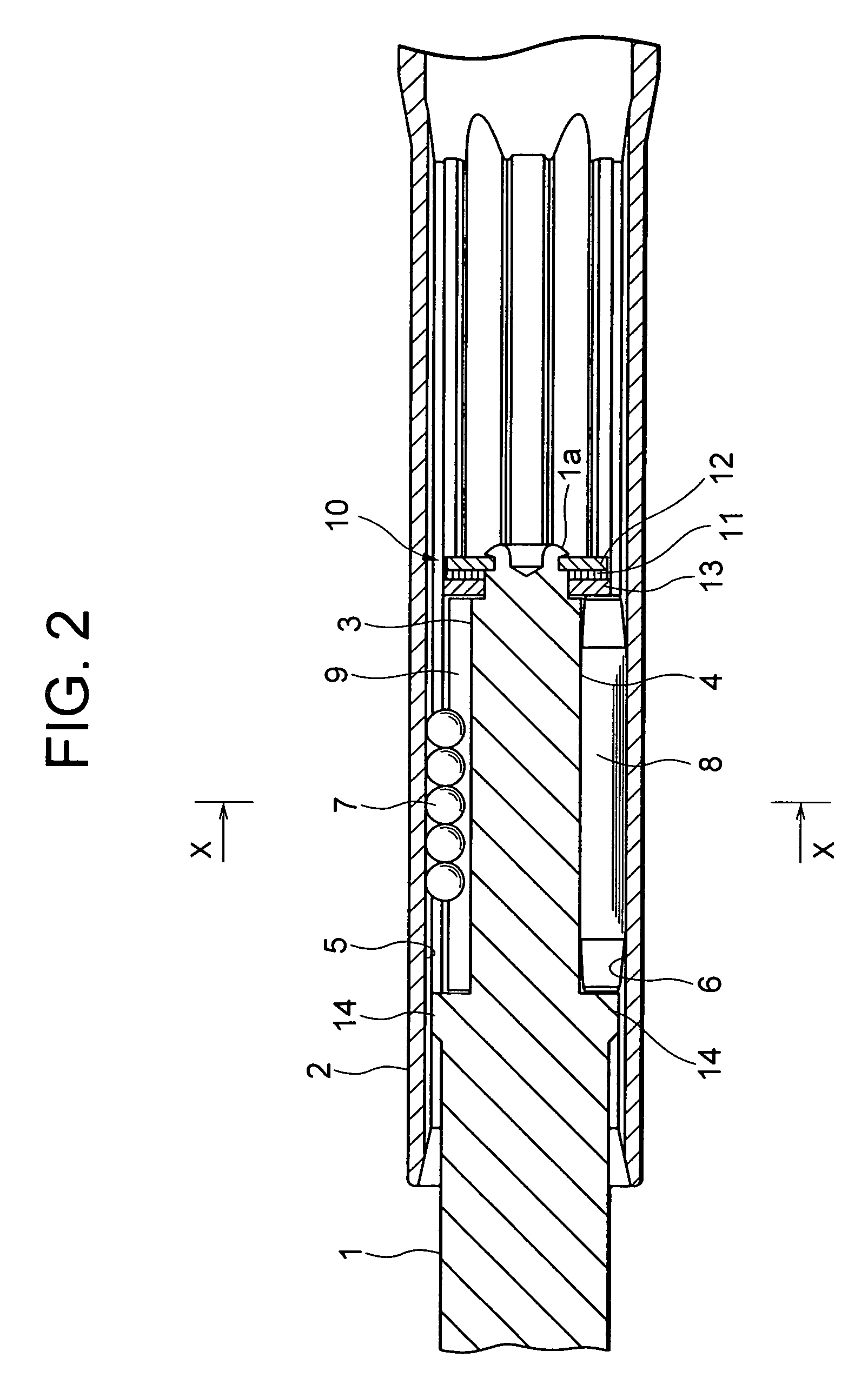
[0035]FIG. 2 is a vertical sectional view of the telescopic shaft for the vehicle steering according to a first embodiment of the present invention.

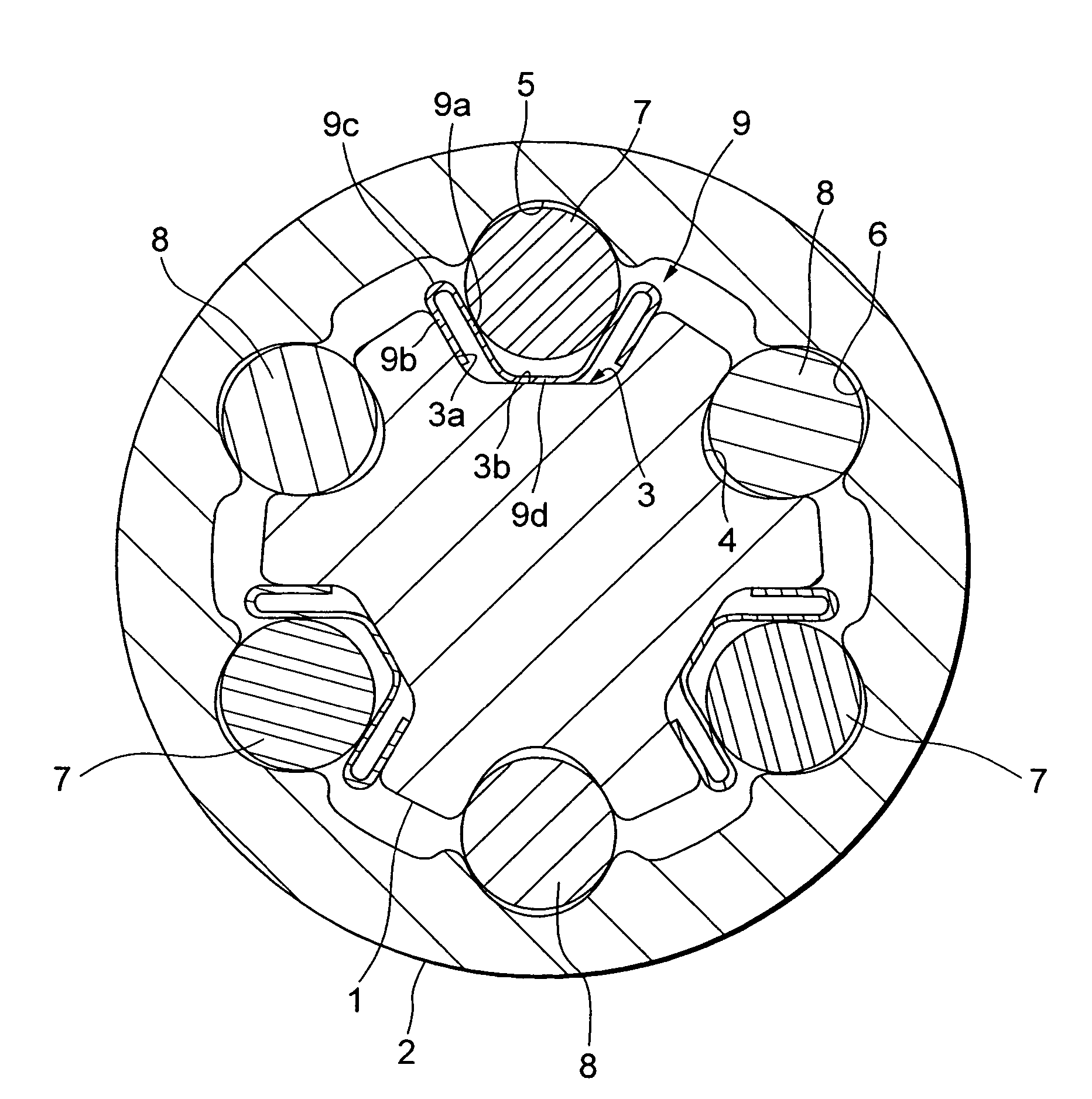
[0036]FIG. 3 is a cross sectional view taken along the line X-X in FIG. 2.

[0037]FIG. 4A is a perspective view of a plate spring according to the first embodiment. FIG. 4B is a perspective view of the plate spring according to a first modified example of the first embodiment. FIG. 4C is a perspective view of the plate spring according to a second modified example of the first embodiment.

[0038]As shown in FIG. 2, the telescopic shaft for the vehicle steering (which will hereinafter be simply referred to as the telescopic shaft) is constructed of a male shaft 1 and a female shaft 2 that are so fitted to each other as to be unable to rotate but to be slidable.

[0039]As shown in FIG. 3, three lines of axis-directional grooves 3 disposed equally at an interval (phase) of 120 degrees in a peripheral direction, are formed in a way that extends al...

second embodiment

[0094]FIG. 5 is a cross sectional view taken along the line X-X in FIG. 2, showing the telescopic shaft for the vehicle steering according to a second embodiment of the present invention.

[0095]FIG. 6A is a perspective view of the plate spring according to the second embodiment. FIG. 6B is a perspective view of the plate spring according to a first modified example of the second embodiment. FIG. 6C is a perspective view of the plate spring according to a second modified example of the second embodiment.

[0096]As shown in FIGS. 5 and 6A, according to the second embodiment, as compared with the first embodiment, the plate thickness of the spherical-member-side contact portion 93a abutting on the spherical member 7 is set thicker than a plate thickness of a portion extending from the shaft-side contact portion 93b to the biasing portion 93c. Thus, according to the second embodiment, the preload balance described above is taken in a way that differentiates the rigidities of the spherical-...

third embodiment

[0102]FIG. 7 is a cross sectional view taken along the line X-X in FIG. 2, showing the telescopic shaft for the vehicle steering according to a third embodiment of the present invention.

[0103]FIG. 8A is a perspective view of the plate spring according to the third embodiment. FIG. 8B is a perspective view of the plate spring according to a first modified example of the third embodiment. FIG. 8C is a perspective view of the plate spring according to a second modified example of the third embodiment.

[0104]As illustrated in FIGS. 7 and 8, according to the third embodiment, as compared with the first embodiment, the spherical-member-side contact portions 96a abutting on the spherical member 7 each is formed substantially in the circular arc shape. With this configuration, the contact surface pressure can be made lower than in the plane shape. According to the third embodiment, the spherical-member-side contact portions 96a abutting on the spherical member 7 each is formed substantially ...


PUM


Abstract

A telescopic shaft for vehicle steering has first and second torque transferring members. The first torque transferring member is interposed, with an elastic body in between, between axial grooves formed in an outer peripheral surface of a male shaft and an inner peripheral surface of a female shaft. The second torque transferring member is interposed between other axial grooves formed in the outer peripheral surface of the male shaft and in the inner peripheral surface of the female shaft. The elastic body has transferring-member-side contact portions contacting the first torque transferring member, shaft-side contact portions contacting groove surfaces of the axial groove of the male shaft or the female shaft, and a biasing portion for elastically urging the transferring-member-side contact portions and the shaft-side contact portions away from each other. Rigidity of the transferring-member-side contact portions is different from that of the shaft-side contact portions.

Description

TECHNICAL FIELD[0001]The present invention relates to a telescopic (extensible / retractable) shaft for a vehicle steering, assembled in a steering shaft of a vehicle and constructed by fitting a male shaft and a female shaft to each other so as to be unable to rotate but to be slidable.BACKGROUND ART[0002]A requirement for a telescopic shaft of a steering mechanism unit of a vehicle includes absorbing an axis-directional displacement during vehicle travel so as to inhibit the transfer of the displacement and vibrations to a steering wheel. Further, another requirement includes a function of shifting a position of the steering wheel in an axis-direction and adjusting this position in order for a driver to obtain a position optimal for driving the vehicle.[0003]In all these cases, the telescopic shaft is required to reduce backlash or rattling noises, a feeling of the backlash on the steering wheel, and slide resistance when sliding in the axis-direction.[0004]Such being the case, a co...

Claims


Application Information

Patent Timeline
Patent Type & Authority Patents(United States)
IPC IPC(8): F16C3/06B62D1/185F16C3/035F16D3/06F16D3/64
CPCB62D1/185F16C3/035F16D3/065F16C29/005F16C29/123F16D3/64F16C2326/24F16C29/007F16C33/60
Inventor YAMADA, YASUHISA
Owner NSK LTD
Why Eureka
Try Eureka