Lever type connector

a connector and lever type technology, applied in the direction of coupling device connection coupling device engagement/disengagement, etc., can solve the problem of difficult to adopt the above-mentioned structure, and achieve the effect of preventing plastic deformation of elements

Inactive Publication Date: 2008-07-29
YAZAKI CORP
View PDF7 Cites 5 Cited by
  • Summary
  • Abstract
  • Description
  • Claims
  • Application Information

AI Technical Summary

Benefits of technology

[0010]In view of the above-described situation, the present invention has an object to provide a lever type connector which is capable of preventing plastic deformation of elements for temporary holding of a movable guide member without forming an access hole by a telescoping shutoff of injection molding.
[0013]Therefore, continuous bending of the elastic arm under the connecting state of the connector housings is prevented. As a result, reduction of temporary connecting performance is prevented. In addition, since the elastic arm is not bent under the temporary or complete connecting state, it is prevented that an external force would act on the elastic arm even when the external force acts on the connector housings. As a result, durability against an external force is improved.
[0014]Furthermore, the release projection, which bends the elastic arm toward the release direction as the connection proceeds, is provided not directly on the first connector housing but on the front holder attached to the first connector housing. Since the space would not become an undercut portion of injection molding, an access hole, which is often made by a telescoping shutoff of injection molding to mold an undercut portion, is not made on the first connector housing for the space. Therefore, it could never happen that water infiltrates into the inside of the connector housings through an access hole. As a result, deterioration of waterproofing and noise-and-vibration performances concerning the first connector is prevented.
[0016]In this way, since the pair of the pawl and the engaging portion offsets from the pair of the release projection and the first slope in a perpendicular plane to the connecting direction, compact design, such as short length in the connecting direction, can be provided.
[0018]In this way, since the second slope, which is disposed on a distal end of the elastic arm, bends the elastic arm toward the release direction by contacting with the release projection of the front holder at the disconnection, the connector housings can be disconnected smoothly.

Problems solved by technology

These structures may produce disadvantageous condition and then it is difficult to adopt the above-mentioned structure actually.

Method used


Image

  • Lever type connector
  • Lever type connector
  • Lever type connector

Examples


Embodiment Construction

[0045]In the following, an embodiment of the present invention will be described with references to the drawings.

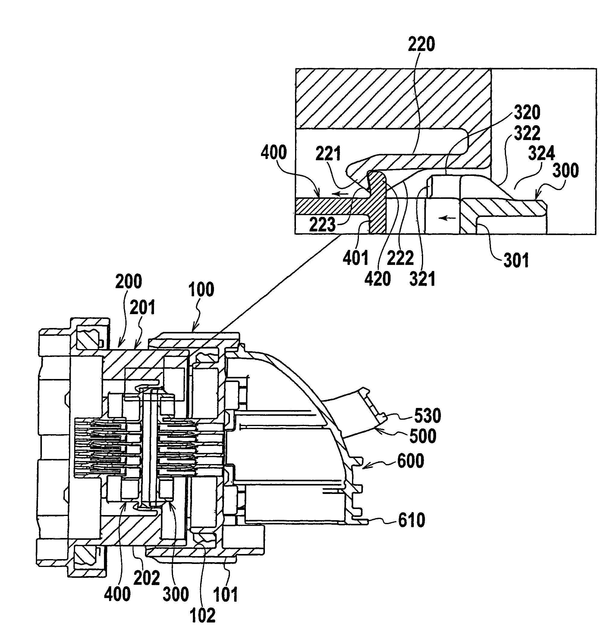
[0046]A lever type connector of this embodiment mainly comprises a female connector 100, a male connector 200, a front holder 300, a movable plate (movable guide member) 400, a lever 500, and a cover 600. The female connector 100 and the male connector 200 are to be connected with each other. The front holder 300 is attached inside a front aperture 102 of a housing (female connector housing) 101 of the female connector 100. The movable plate 400 is attached inside a hood 202 of a connector housing (male connector housing) 201 of the male connector 200. The movable plate 400 is attached inside a front aperture 202a of the hood 202 and slidable in a connecting direction (a forward and backward direction) within the food 202. The lever 500 is attached to an outer side of the female connector 100. The cover 600 is attached to the female connector 100 in order to cover a backs...


PUM


Abstract

A lever type connector comprises two connector housings, a front holder, a movable guide member fixed within one of the connector housings, and a movable guide member slidably attached to another of the connector housings. The movable guide member protects male terminals at a temporary holding position and is slid by the front holder toward an end position during connection. A elastic arm for temporarily holding the movable guide member is provided within the connector with the male terminals. A release projection is provided on the front holder. A space for stowing the elastic arm, which has restored its bending, is secured behind the release projection. According to the lever type connector can prevent plastic deformation of the elastic arm for temporary holding of the movable guide member without forming an access hole by a telescoping shutoff of injection molding.

Description

BACKGROUND OF THE INVENTION[0001]1. Field of the Invention[0002]The present invention relates to a lever type connector having a movable guide member (also called “movable plate”), which is installed in a connector housing having male terminals therewithin, protects distal ends of the male terminals, and assist respective connections between male and female terminals.[0003]2. Description of the Related Art[0004]FIG. 1 to FIG. 6 show one example of a conventional lever type connector described in Japanese Patent No. 2946000. As shown in FIG. 1 and FIG. 2, the lever type connector comprises a male connector 910, a female connector 920 and a movable guide member 930. The female connector 920 includes an aperture 922 for stowing the male connector 910. The movable guide member 930 is installed slidably within the aperture 922 and slides a connecting direction of the male connector 910. The movable guide member 930 also protects and guides terminals 960 projecting within the aperture 920...

Claims


Application Information

Patent Timeline
Patent Type & Authority Patents(United States)
IPC IPC(8): H01R13/62
CPCH01R13/62938H01R43/26H01R2201/26H01R13/62955H01R13/631H01R13/4538
Inventor IKEYA, KENICHICABANGAL, RONALD ALANINOUE, HIDEKI
Owner YAZAKI CORP
Why Eureka
Try Eureka