
Keyboard apparatus

a technology of keyboard and spherical body, which is applied in the direction of strings of musical instruments, instruments, electrophonic musical instruments, etc., can solve the problems of sudden decrease in the amount of bend, and achieve the effect of simplifying construction and ensuring load chang

Active Publication Date: 2008-07-22
YAMAHA CORP
View PDF11 Cites 13 Cited by
  • Summary
  • Abstract
  • Description
  • Claims
  • Application Information

AI Technical Summary

Benefits of technology

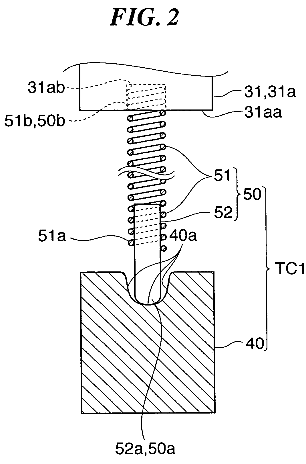
The present invention provides a keyboard apparatus that can give a natural key depression feeling with a definite and positive load change. This is achieved by a keyboard apparatus that includes a support member, a plurality of pivots, a plurality of keys, a key return device, a key touch feeling-imparting mechanism, and a mass member. The key touch feeling-imparting mechanism includes a receiving part and an elastic engaging unit that is disposed such that it can bend during key depression and decrease in bend as the sliding frictional state between the elastic engaging unit and the receiving part changes. This allows for a natural key depression feeling dependent on the manner of key depression. The elastic engaging unit is disposed such that it can bend in one direction when the associated key is in a non-depressed state, and decrease in bend as the sliding frictional state between the elastic engaging unit and the receiving part changes. This allows for a natural key depression feeling dependent on the manner of key depression. The keyboard apparatus is simplified in construction and reduces the weight of the keyboard.

Problems solved by technology

Further, the sudden decrease in the amount of bend is caused by a change in the sliding frictional state between the other end of the elastic engaging unit and the receiving part.

Method used


Image

  • Keyboard apparatus
  • Keyboard apparatus
  • Keyboard apparatus

Examples


first embodiment

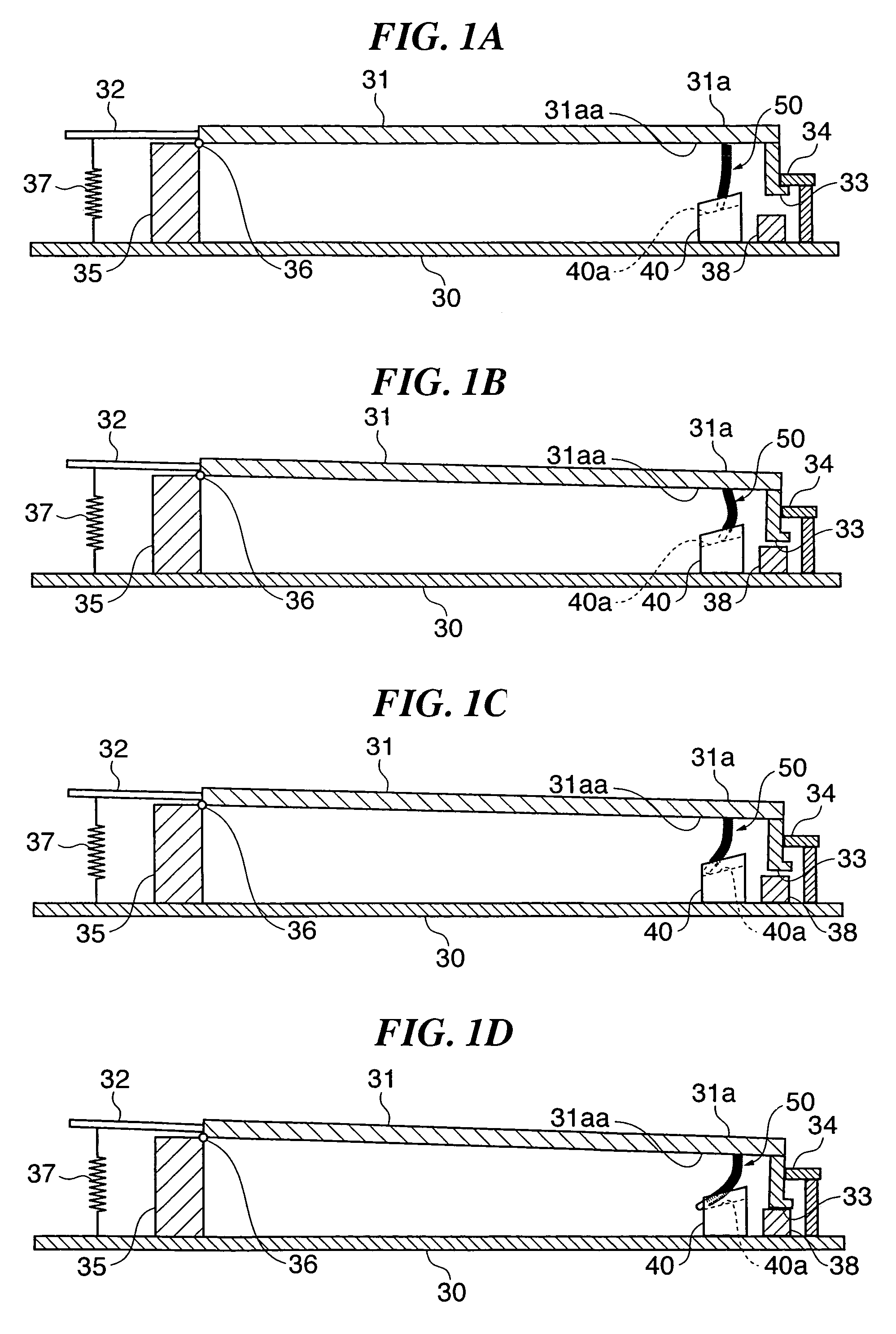
[0071]FIGS. 1A to 1D are longitudinal cross-sectional views of a keyboard apparatus according to the present invention. FIG. 1A shows the keyboard apparatus in a non-key-depressed state; FIGS. 1B and 1C show the same in states during key depression; and FIG. 1D shows the same in a key depression-terminated state. As shown in FIG. 1A, a support member 30 has a support column 35 as a key support provided thereon, and a key body 31 is supported by the support column 35 for vertical swinging motion about a pivot 36 provided on the top of the support column 35. In the following description, a free end side of the key body 31 (right side as viewed in FIG. 1A) will be referred to as “the front side”. In FIGS. 1A to 1D, a white key is shown as the key body 31, by way of example.

[0072]An extended part 32 extends rearward from the pivot 36 of the key body 31, and a key return spring 37 is stretched as a key return device between the extended part 32 and the support member 30, for always pulli...

second embodiment

[0082]More specifically, the lower end 50a of the elastic engaging unit 50 and the guide rail 40a are in a state where an appropriate friction is produced therebetween, and the static frictional state between them is maintained from the state shown in FIG. 3A to the state shown in FIG. 3B. Further, when the key touch feeling-imparting mechanism is in the state shown in FIG. 3B, the position of the key operating part 31a is lower than when the same is in the state in FIG. 3A, and hence the elastic engaging unit 50 (specifically, the coil spring 51) is further bent such that it generally protrudes in the same direction (toward the front side) as it does beforehand. Hereafter, the increase in the amount of bend described above will be referred to as “additional bend”, in the present embodiment as well as a second embodiment described hereinafter. The reaction force produced by the additional bend of the coil spring 51 acts on the key body 31, and insofar as the static frictional state ...

third embodiment

[0132]Next, a description will be given of the present invention.

[0133]A keyboard apparatus according to the third embodiment of the present invention is distinguished from the keyboard apparatus according to the second embodiment in the constructions of the key touch feeling-imparting mechanism, fixing members associated therewith, and the like, but otherwise has the same construction as that of the second embodiment.

[0134]FIG. 6A is a side view of a key touch feeling-imparting mechanism TC3 of the keyboard apparatus according to the third embodiment. FIG. 6B is a fragmentary side view of a key touch feeling-imparting mechanism TC4 as a variation of the keyboard apparatus according to the third embodiment.

[0135]A common base 80 shown in FIG. 6A is constructed similarly to the common base 60 of the second embodiment, and has a white key-receiving part 80aW and a black key-receiving part 80aB corresponding to the white key-receiving part 60aW and the black key-receiving part 60aB of ...


PUM


Abstract

A keyboard apparatus which is capable of imparting a natural key depression feeling with a definite and positive load change, with a simplified construction. A key touch feeling-imparting mechanism imparts a predetermined key touch feeling to a key when it is depressed. The key touch feeling-imparting mechanism is comprised of a receiving part provided on a support member, and an elastic engaging unit that has one end thereof held by a key operating part of an associated key and another end thereof slidably engaged with the receiving part. The elastic engaging unit is disposed such that the elastic engaging unit is bent during a forward stroke of key depression caused by a key depressing operation to give a reaction force to the associated key, and the elastic engaging unit suddenly decreases in an amount of bend thereof due to a change in a sliding frictional state between the other end thereof and the receiving part during the forward stroke of key depression, to thereby decrease the reaction force given to the associated key.

Description

BACKGROUND OF THE INVENTION[0001]1. Field of the Invention[0002]The present invention relates to a keyboard apparatus that can impart a key depression feeling characteristic to a key when the key is depressed.[0003]2. Description of the Related Art[0004]Conventionally, an electronic piano artificially realizes a key depression feeling or a key touch feeling, such as that of an acoustic piano. However, for a keyboard apparatus, such as a portable keyboard, that is desired to be small in size, low in price, and light in weight, it is not easy to provide a mechanism (key touch feeling-imparting mechanism) that realizes the key touch feeling mentioned above, and even when the mechanism can be provided, it is desired to be as simple as possible.[0005]To meet the requirement, Japanese Utility Model Publication (Kokoku) No. S59-39740 has proposed a keyboard apparatus in which a leaf spring having an end thereof bent into the shape of “L” is attached to an instrument body, and which is conf...

Claims


Application Information

Patent Timeline
Patent Type & Authority Patents(United States)
IPC IPC(8): G10C3/12
CPCG10H1/346
Inventor FUNAKI, TOMOYUKIMISHIMA, JUNICHI
Owner YAMAHA CORP
Learn More