
Self-fastening cage surrounding a magnetic resonance device and methods thereof

a magnetic resonance device and self-fastening technology, applied in the field of self-fastening cages, can solve the problems of inconvenient use of simple permanent magnet structures, such as c-magnets or h-magnets, and the need for much more complex assemblies in order to achieve the required magnetic field

Active Publication Date: 2008-07-15
ASPECT IMAGING
View PDF9 Cites 31 Cited by
  • Summary
  • Abstract
  • Description
  • Claims
  • Application Information

AI Technical Summary

Benefits of technology

The solution provides a cost-effective and efficient method to achieve a stable and uniform magnetic field, allowing for high-resolution magnetic resonance spectroscopy by utilizing a combination of side-magnets, pole-pieces, and adjustable corner-magnets to enhance the magnetic field strength and uniformity.

Problems solved by technology

In order to achieve a uniform and strong magnetic field using permanent magnet material, the use of simple permanent magnet structures, like C-magnet or H-magnet, is not suitable.
Therefore, much more complex assemblies are needed in order to achieve the required magnetic field.

Method used


Image

  • Self-fastening cage surrounding a magnetic resonance device and methods thereof
  • Self-fastening cage surrounding a magnetic resonance device and methods thereof
  • Self-fastening cage surrounding a magnetic resonance device and methods thereof

Examples


Embodiment Construction

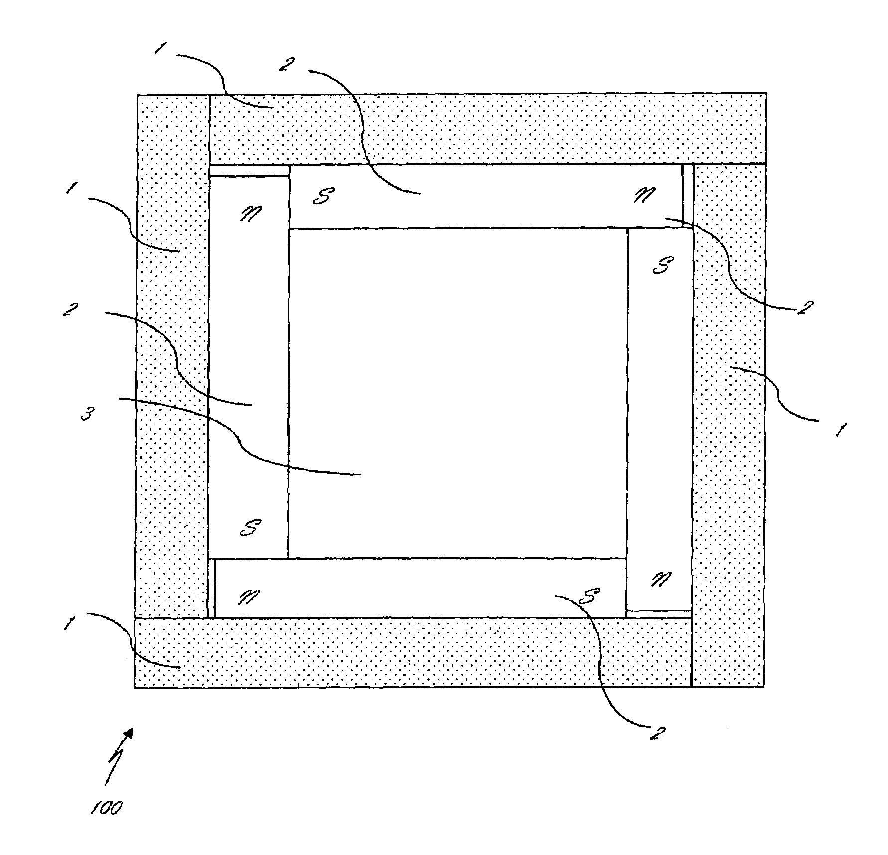
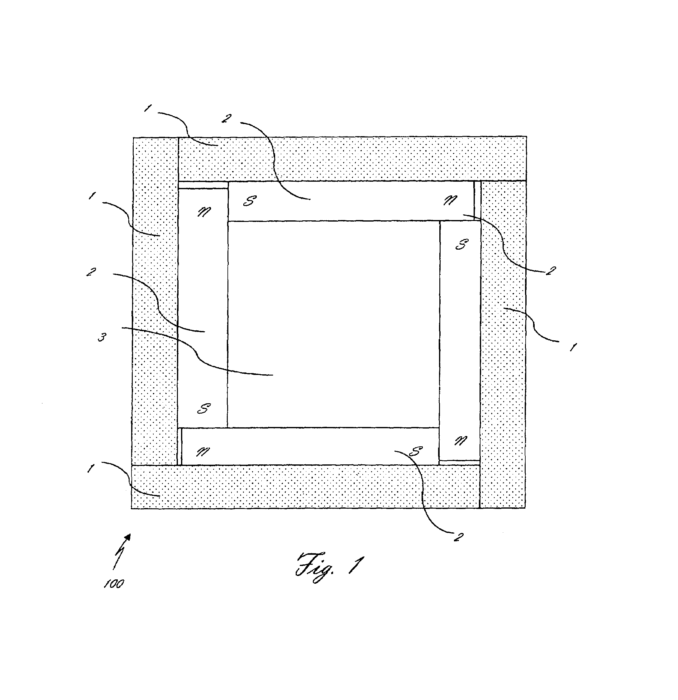
[0052]The following description is provided, alongside all chapters of the present invention, so that to enable any person skilled in the art to make use of said invention and sets forth the best modes contemplated by the inventor of carrying out this invention. Various modifications, however, will remain apparent to those skilled in the art, since the generic principles of the present invention have been defined specifically to provide an efficient self-fastening cage of a MRD (100) for providing a homogeneous, stable and uniform magnetic field therein, characterized by an outside shell comprising at least three flexi-jointed superimposed walls (1) and methods thereof.

[0053]The term ‘self-fastening’ refers hereinafter to a strong magnetic connection between the side-magnets and the cage walls. The magnets' edges are attracted to each other such that a closed form is provided. The cage, magnetically attracted to the side-magnets, supports itself without need for another connection.

[...


PUM


Abstract

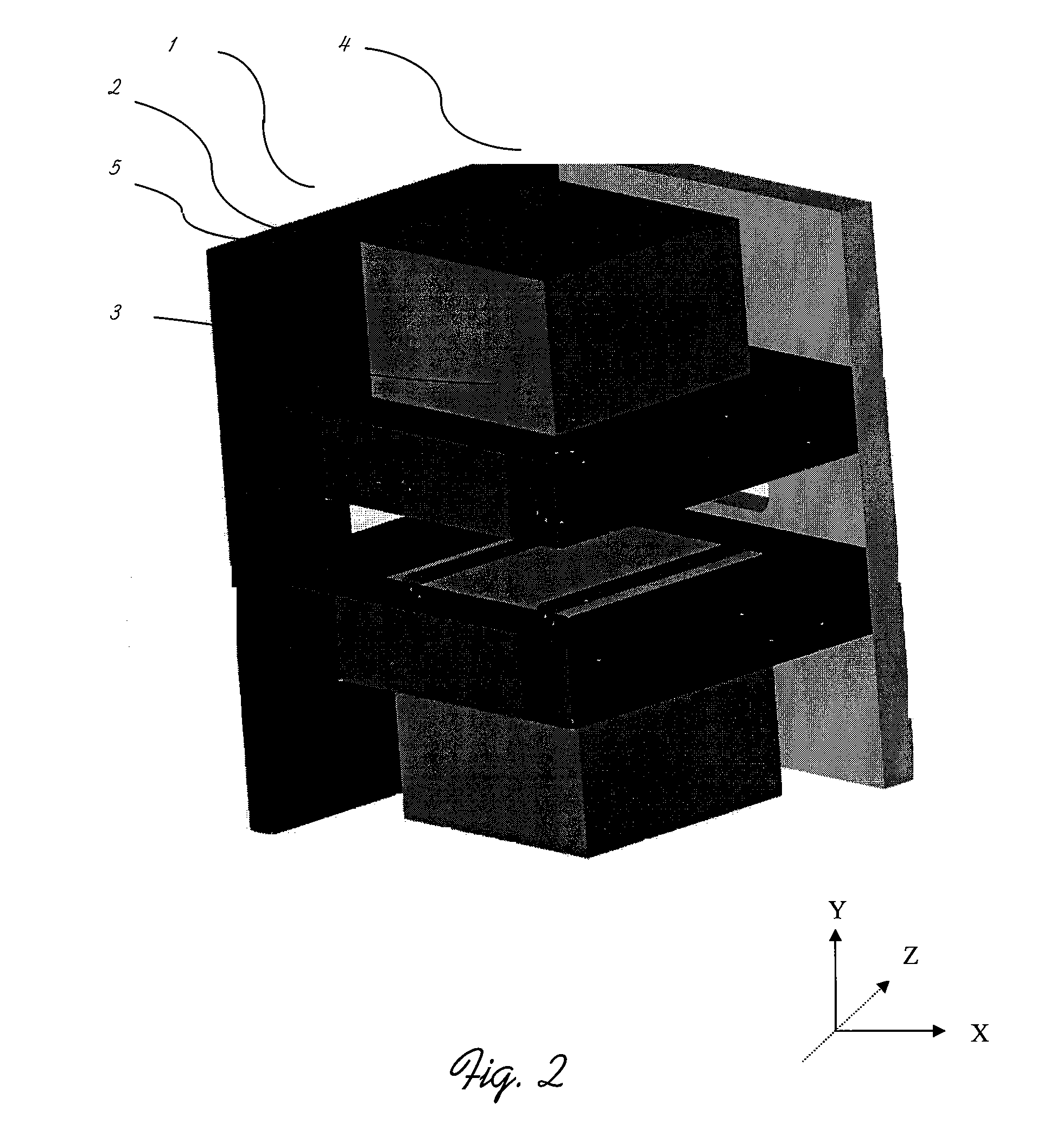
The present invention discloses a novel self-fastening cage of a magnetic resonance device (MRD) (100) for providing a homogeneous, stable and uniform magnetic field therein, characterized by an outside shell comprising at least three flexi-jointed superimposed walls (1). In a technology of self-fastening cage, the invention teaches an effective multi-streamed MRD comprising a cage including a closed magnetic circuit constructed from strong permanent magnets; and an optional shimming mechanism selected from an array of active shim coils, passive shimming elements or any combination thereof; a contained cavity within which the magnetic field strength is approximately uniform; and a means, such as a plurality of conveyor belts, pipes or any other transportation means by which a plurality of samples are introduced into the region of uniform magnetic field; such that magnetic resonance measurements are made on a plurality of samples within the region of uniform magnetic field. The invention depicts a cost effective method for obtaining a self-fastening cage of a MRD (100) characterized by an outside shell comprising superimposing at least three flexi-jointed walls (1) so that a homogeneous, stable and uniform magnetic field is provided therein.

Description

[0001]This application claims the priority date of U.S. Provisional Patent Application 60 / 732,654 filed Nov. 03, 2005.FIELD OF THE INVENTION[0002]The present invention generally relates to a self-fastening cage surrounding a magnetic resonance device (MRD) for providing a homogeneous, stable and uniform magnetic field therein. More specifically, the present invention relates to a self-fastening cage characterized by an outside shell comprising at least three flexi-jointed superimposed walls.BACKGROUND OF THE INVENTION[0003]Electromagnetic based instruments for measuring properties of matter or identifying its composition are well known. Magnetic resonance spectroscopy is one of the principal measuring techniques used to obtain physical, chemical and structural information about a molecule. In order to be able to perform magnetic resonance spectroscopy with high resolution capabilities providing a high quality image (i.e., resolution and contrast) the magnetic field used must be extr...

Claims


Application Information

Patent Timeline
Patent Type & Authority Patents(United States)
IPC IPC(8): G01V3/00
CPCG01R33/383G01R33/307G01R33/3815G01R33/3875G01R33/3873
Inventor RAPOPORT, URI
Owner ASPECT IMAGING
Learn More