
Lighted plier hand tool apparatus

a hand tool and plier technology, applied in the field of hand tools, can solve the problems of not always being practical, not always being located in the outlet, and not always being well lit in the work environmen

Inactive Publication Date: 2008-07-15
READYMAX
View PDF6 Cites 36 Cited by
  • Summary
  • Abstract
  • Description
  • Claims
  • Application Information

AI Technical Summary

Benefits of technology

"The present invention provides a lighted plier hand tool apparatus with an illumination device that can be directly connected to the hub device of the pliers, allowing for high intensity light to illuminate the work area. The hand tool apparatus includes a hub device with a passage for the illumination device to pass through. The pliers have handles, jaw portions, and pivot portions, with the pivot portions interconnected to allow for relative movement of the jaw portions. The illumination device can be adjusted for its direction and width, and a battery box can be included for powering the LED light source. The pliers can also be magnetically retained together using a magnetic coupling device. The technical effects of the invention include improved visibility and ease of use in low-light environments, as well as a more compact and sleek appearance."

Problems solved by technology

Poorly lit work environments will always pose additional risks to any personnel operating hand tools.
This problem is particularly troublesome for industrial application where equipment that is located next to other components that can easily be damaged or that present a hazard to the technician, such as exposed high-voltage sources or heavy equipment.
While external lighting is an obvious solution, it may not always be practical due to space and power source limitations where such tools are to be applied.
Such outlets, of course, are not always located near the equipment that is to be serviced.
Furthermore, the light may relatively large so that technicians may not normally carry them when inspecting and adjusting equipment.
One significant problem with most of these lighted hand tool approaches is that either the light generated by the tool is of lower intensity and insufficient, or the addition of the light impair the use of the tool.

Method used


Image

  • Lighted plier hand tool apparatus
  • Lighted plier hand tool apparatus
  • Lighted plier hand tool apparatus

Examples


Embodiment Construction

[0036]While the present invention will be described with reference to a few specific embodiments, the description is illustrative of the invention and is not to be construed as limiting the invention. Various modifications to the present invention can be made to the preferred embodiments by those skilled in the art without departing from the true spirit and scope of the invention as defined by the appended claims. It will be noted here that for a better understanding, like components are designated by like reference numerals throughout the various figures.

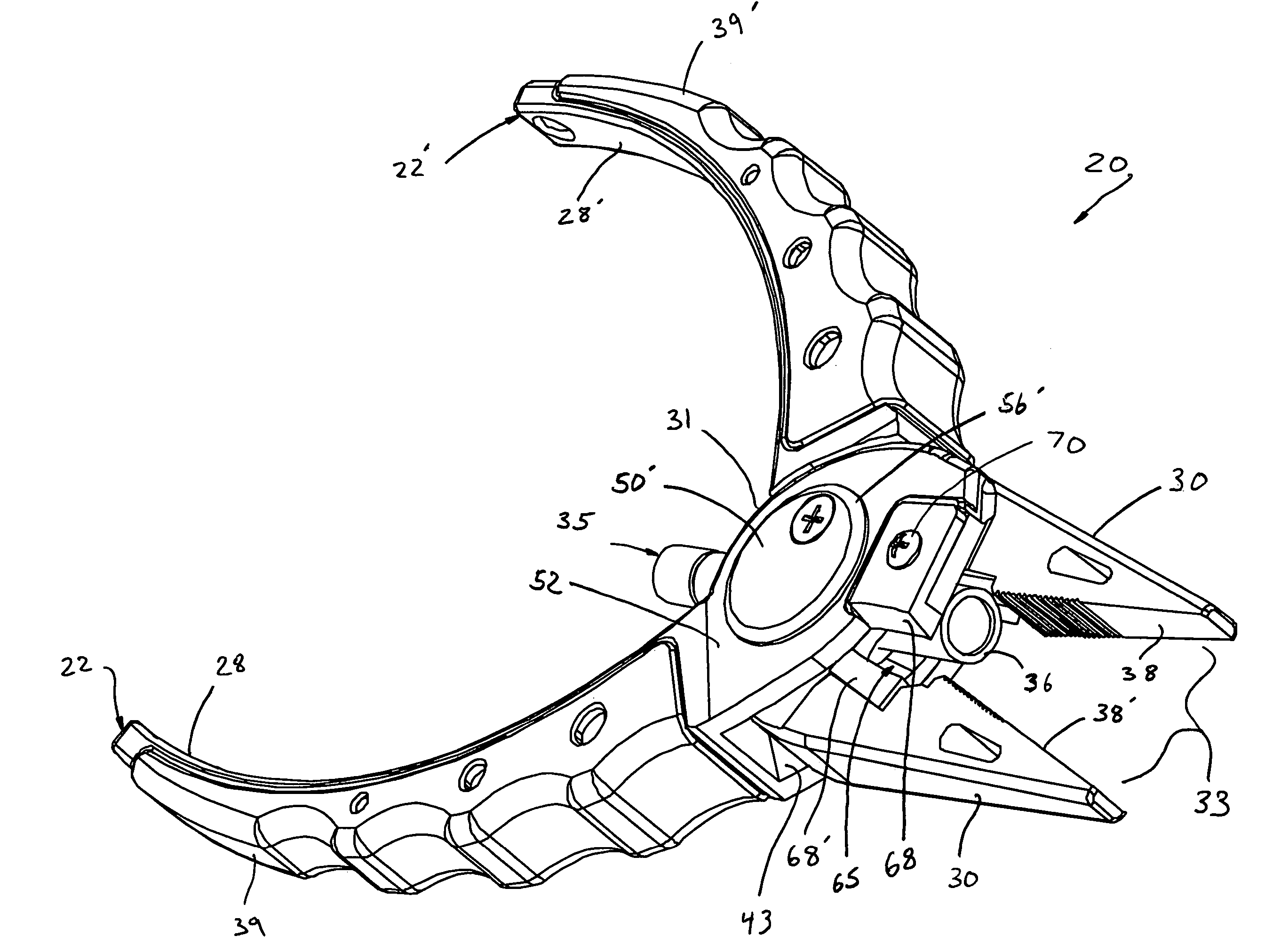
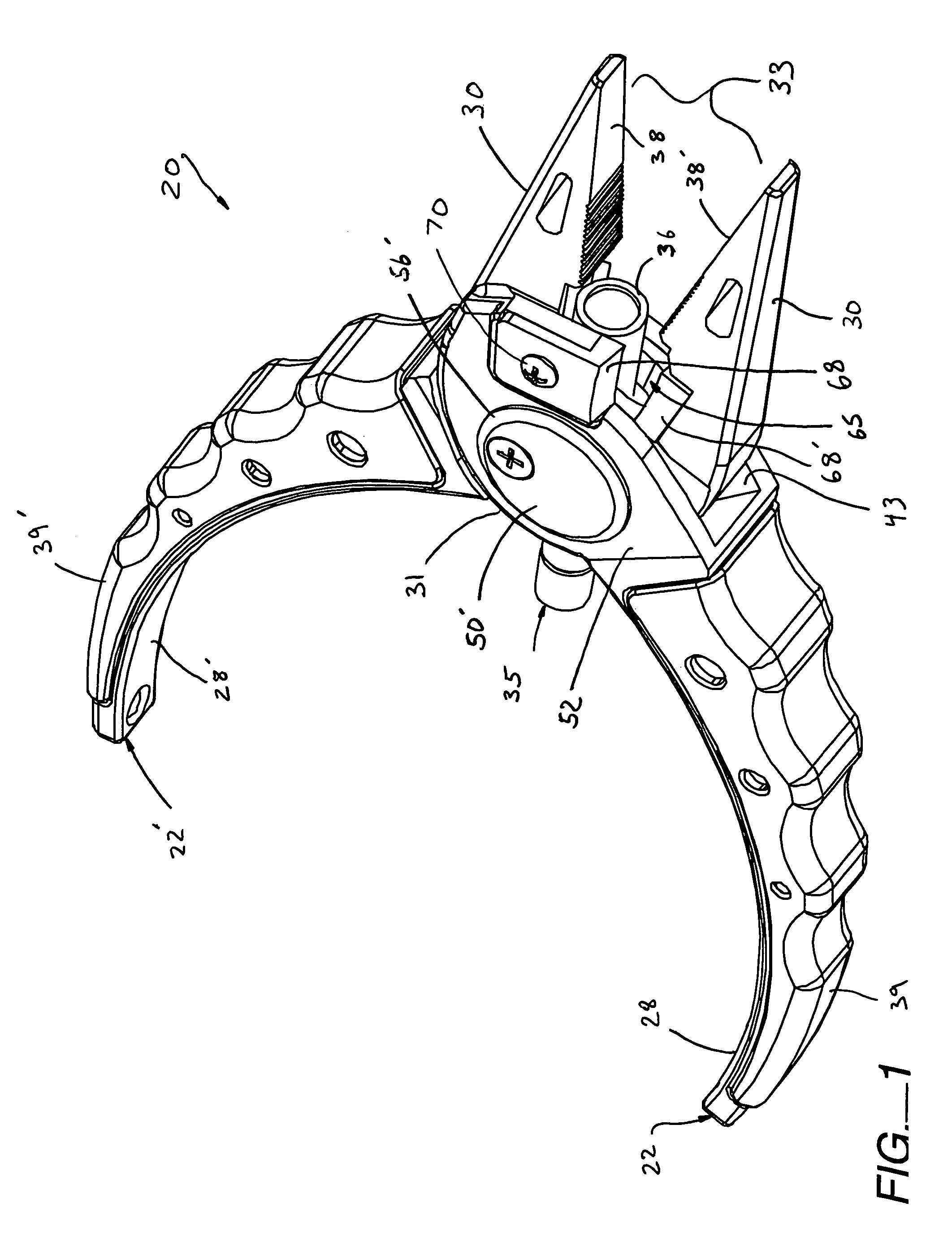
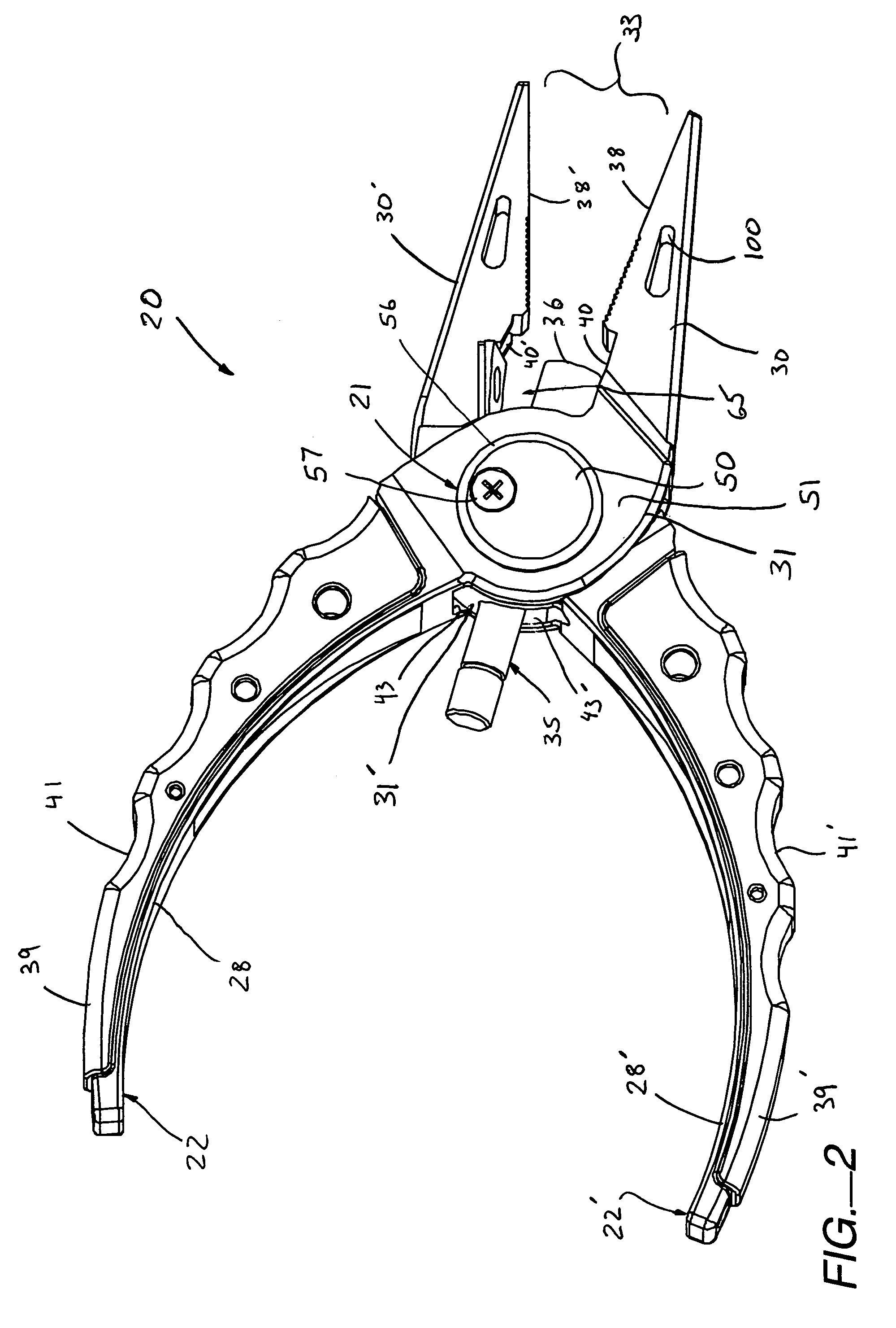
[0037]Referring now to FIGS. 1-5, a lighted plier hand tool apparatus, generally designated 20, is provided having a pivoting hub device 21 and a pair of interconnecting plier members 22, 22′. The hub device 21 includes a first opening (25, 25′), an opposed second opening (26, 26′), and a passage (27, 27′) (FIGS. 7 and 8) therethrough extending from the first opening to the second opening. The plier hand tool apparatus further incl...


PUM


Abstract

A lighted plier hand tool apparatus including a pivoting hub device containing a first opening, an opposed second opening, and a passage therethrough extending from the first opening to the second opening. The plier hand tool apparatus further includes a first plier member and a second plier member. Each plier member includes a respective handle portion, a jaw portion, and an intermediate pivot portion therebetween. Each respective pivot portion defines a respective bore section formed for aligned receipt of the hub device therein. Such receipt interconnects the first and second plier members together to enable relative pivotally movement of the respective jaw portions at a work area between an opened condition and a closed condition. The hand tool apparatus further includes an illumination device having an illumination portion outputting a light beam from one end of an elongated body section. The body section of the assembly is formed and dimensioned for receipt in the passage of the hub device such that the illumination portion terminates at the work area for illumination thereof.

Description

RELATED APPLICATION DATA[0001]The present application claims priority under 35 U.S.C. §119 to U.S. Provisional application Ser. No. 60 / 701,248, naming Clausen et al as inventors, filed Jul. 20, 2005, and entitled A LIGHTED PLIER AND TOOL APPARATUS, which is incorporated herein by reference in their entirety and for all purposes.FIELD OF THE INVENTION[0002]The present invention relates to hand tools, and more particularly, relates to lighted plier hand tool apparatuses.BACKGROUND OF THE INVENTION[0003]Poorly lit work environments will always pose additional risks to any personnel operating hand tools. This problem is particularly troublesome for industrial application where equipment that is located next to other components that can easily be damaged or that present a hazard to the technician, such as exposed high-voltage sources or heavy equipment.[0004]While external lighting is an obvious solution, it may not always be practical due to space and power source limitations where such...

Claims


Application Information

Patent Timeline
Patent Type & Authority Patents(United States)
IPC IPC(8): B25B23/18F21V33/00B25B7/02
CPCB25G1/102B25B7/08F21V33/0084
Inventor CLAUSEN, EIVINDBRAUNER, BILL E.
Owner READYMAX
Learn More