
Seat for vehicle

a technology for vehicles and seats, applied in the field of vehicles seats, can solve the problems of high manufacturing cost, impair assembly or maintenance, etc., and achieve the effect of simple construction

Inactive Publication Date: 2008-07-15
TOYOTA SHATAI KK
View PDF14 Cites 32 Cited by
  • Summary
  • Abstract
  • Description
  • Claims
  • Application Information

AI Technical Summary

Benefits of technology

[0007]It is accordingly an object of the present invention to provide vehicle seats that can automatically release the rotation lock condition of the seat body with the appropriate timing and without using any dedicated actuator, such as an electric motor for operating the rotation lock mechanism, so that convenience can be secured for the occupant.
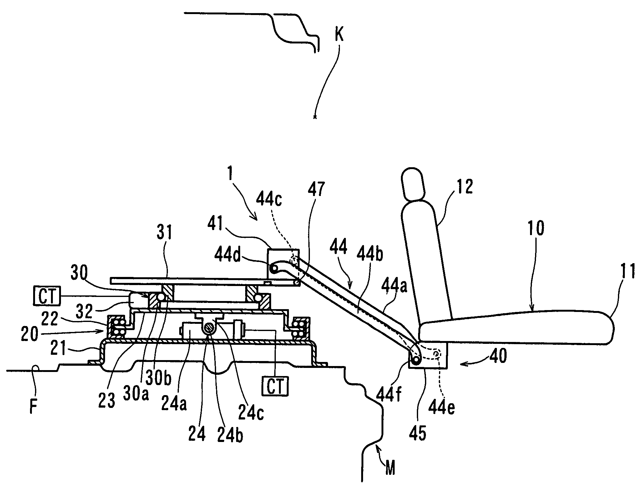
[0009]According to a vehicle seat corresponding to one embodiment of the present invention as, in a condition in which a seat body faces the front side of a vehicle, a rotation lock condition of the seat body is unlocked by operating a slide mechanism to some degree so that a member that can move thereupon, moves and interacts with a rotation lock mechanism. Accordingly, it is possible to release the rotation lock condition without using a dedicated actuator such as an electric motor for operating the rotation lock mechanism as in the prior art. As a result, increased manufacturing costs can be avoided. Also, it is not necessary to provide a space for receiving the actuator as in the prior art. Further, since there is no need to use a dedicated actuator for operating the rotation lock mechanism as in the prior art, it is not necessary to provide electric wiring for the actuator. This may lead to increased workability of assembly or maintenance for the vehicle seat.
[0011]According to a vehicle seat corresponding to another embodiment of the present invention, in addition to the above effect, the operation of each mechanism and each portion is automatically performed in predetermined sequences. Therefore, it is possible to increase the usability of the vehicle seat.
[0013]According to a vehicle seat corresponding to still a further embodiment of the present invention, it is possible to reliably obtain the above effects with a relatively simple construction. Instead of the nut directly interacting with a lock plate, it is also possible for the nut to indirectly interact with the lock plate via an additional member.

Problems solved by technology

This may lead to high manufacturing costs.
This may impair, for example, the workability of assembly or maintenance.

Method used


Image

  • Seat for vehicle
  • Seat for vehicle
  • Seat for vehicle

Examples


Embodiment Construction

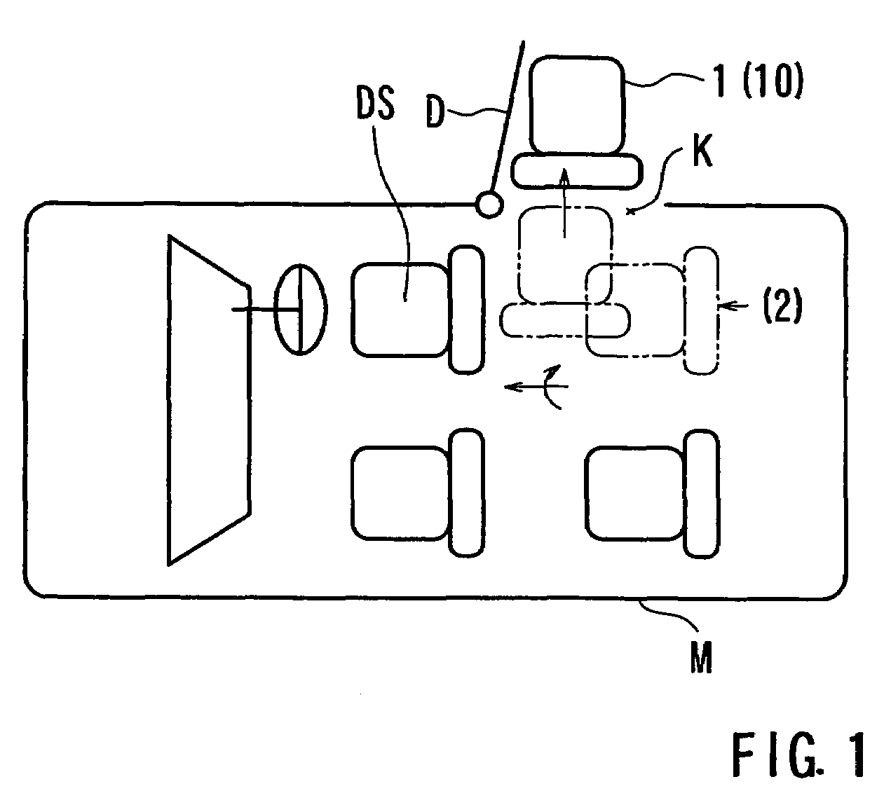
[0026]An embodiment of the present invention will be described with reference to FIGS. 1 to 12. As shown in FIG. 1, this embodiment exemplifies a vehicle seat 1 that is arranged as a second row seat behind a driver's seat DS. In FIG. 1, a door D in the right side (the upper side in FIG. 1) of a vehicle M is opened, and a seat body 10 has been moved to the exterior by way of a door opening K. In the vehicle seat 1 of this embodiment, the seat body 10 can move in the longitudinal direction (the right and left direction in FIG. 1) of the vehicle and can rotate by approximately 90 degrees between a position where the seat body 10 faces the front side of the vehicle and a position where the seat body 10 faces the door opening K. Further, the seat body 10 can move in the lateral direction of the vehicle (the vertical direction in FIG. 1) while facing the door opening K.

[0027]As shown in FIGS. 2 to 4, the vehicle seat 1 includes the seat body 10, a first slide mechanism 20 for moving the s...


PUM


Abstract

The present invention provides a mechanism that can release the rotation lock mechanism without using an actuator.In the present vehicle seat, a nut (73) is moved upon rotation of a screw shaft (72) so that the seat body is moved in the lateral direction of the vehicle. When the nut (73) is moved by a desired distance, a guide roller (69) is pushed so that an operation arm (66) is moved parallel with the guide roller. As a result, a lock plate (64) is rotated in an unlock direction so that a claw (64a) is disengaged from a striker (61).

Description

TECHNICAL FIELD[0001]This invention relates to vehicle seats that enables an elderly person, a physically challenged person or other such persons (which will be hereinafter simply referred to as a passenger or an occupant) to easily get into and out of a vehicle.BACKGROUND ART[0002]Recently, various types of seats have been provided for this kind of situation. For example, a vehicle seat is disclosed in JP 9-39622. This vehicle seat has a rotation mechanism for rotating a seat body, a longitudinal slide mechanism for sliding the seat body in the longitudinal direction of the vehicle, and an ascent / descent mechanism that lowers the seat body to a lower position while moving the seat body to the exterior of the vehicle, under the conditions that the seat body is directed to the door opening by the rotation mechanism.[0003]According to this vehicle seat, by moving the seat body to the exterior of the vehicle and lowering the seat body to a height close to the road surface, the passenge...

Claims


Application Information

Patent Timeline
Patent Type & Authority Patents(United States)
IPC IPC(8): A47C1/00B60N2/02A61G3/00B60N2/06B60N2/14B60N2/16B60N2/24
CPCB60N2/245B60N2/14B60N2/06B60N2/08
Inventor KUSANAGI, HIROKISUGA, YASUOIWATANI, MASAMITSU
Owner TOYOTA SHATAI KK
Learn More