Eureka AIR delivers breakthrough ideas for toughest innovation challenges, trusted by R&D personnel around the world.

Method and apparatus for reducing the infrared and radar signature of a vehicle

a technology of infrared and radar signature, which is applied in the direction of transportation and packaging, other domestic articles, efficient propulsion technologies, etc., can solve the problems of reducing the performance and the range of the aircraft, affecting the aerodynamics of the aircraft, and additional radar-absorptive materials carrying additional weight, so as to achieve the effect of reducing the infrared signature and the radar signature of the vehicl

Active Publication Date: 2008-07-08
BELL HELICOPTER TEXTRON INC
View PDF7 Cites 6 Cited by
  • Summary
  • Abstract
  • Description
  • Claims
  • Application Information

AI Technical Summary

Benefits of technology

[0010]One significant advantage of the present invention is that the infrared signature and the radar signature of a vehicle can both be reduced simultaneously, without causing adverse effects in either of these areas of concern.
is that the infrared signature and the radar signature of a vehicle can both be reduced simultaneously, without causing adverse effects in either of these areas of concern.

Problems solved by technology

Although these methods can be very effective when properly employed, each of these methods has drawbacks.
In most cases, the addition of infrared-insulative and infrared-absorptive materials to the outer skin of the aircraft represents a significant addition of weight to the aircraft and may interfere with the aerodynamics of the aircraft, reducing the performance and the range of the aircraft.
Unfortunately, additional radar-absorptive materials carry with them additional weight, and shapes optimized for minimal radar signature generally exhibit less-than ideal aerodynamic characteristics.
In many cases, attempts to reduce the signature in one area of concern actually increases the signature in the other.

Method used


Image

  • Method and apparatus for reducing the infrared and radar signature of a vehicle
  • Method and apparatus for reducing the infrared and radar signature of a vehicle
  • Method and apparatus for reducing the infrared and radar signature of a vehicle

Examples


Embodiment Construction

[0029]While the making and using of various embodiments of the present invention are discussed in detail below, it should be appreciated that the present invention provides many applicable inventive concepts, which can be embodied in a wide variety of specific contexts. The specific embodiments discussed herein are merely illustrative of specific ways to make and use the invention and do not delimit the scope of the invention.

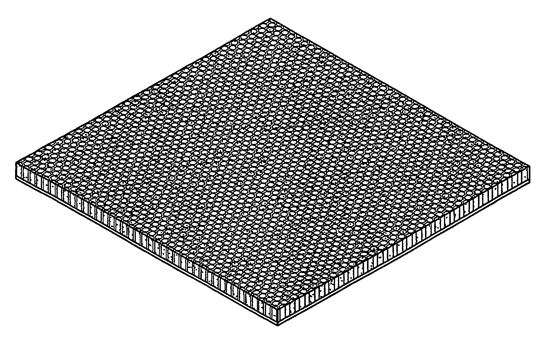
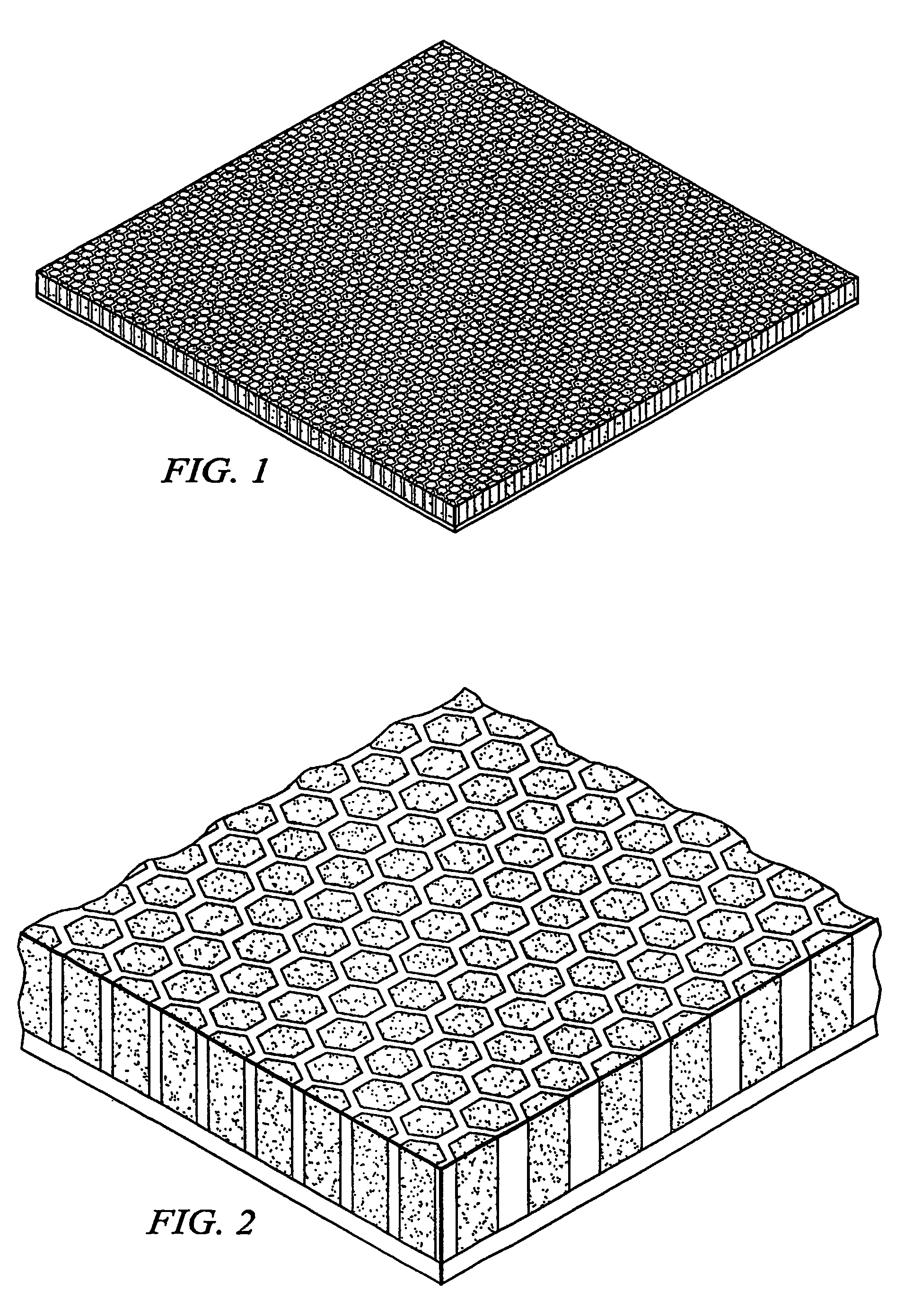
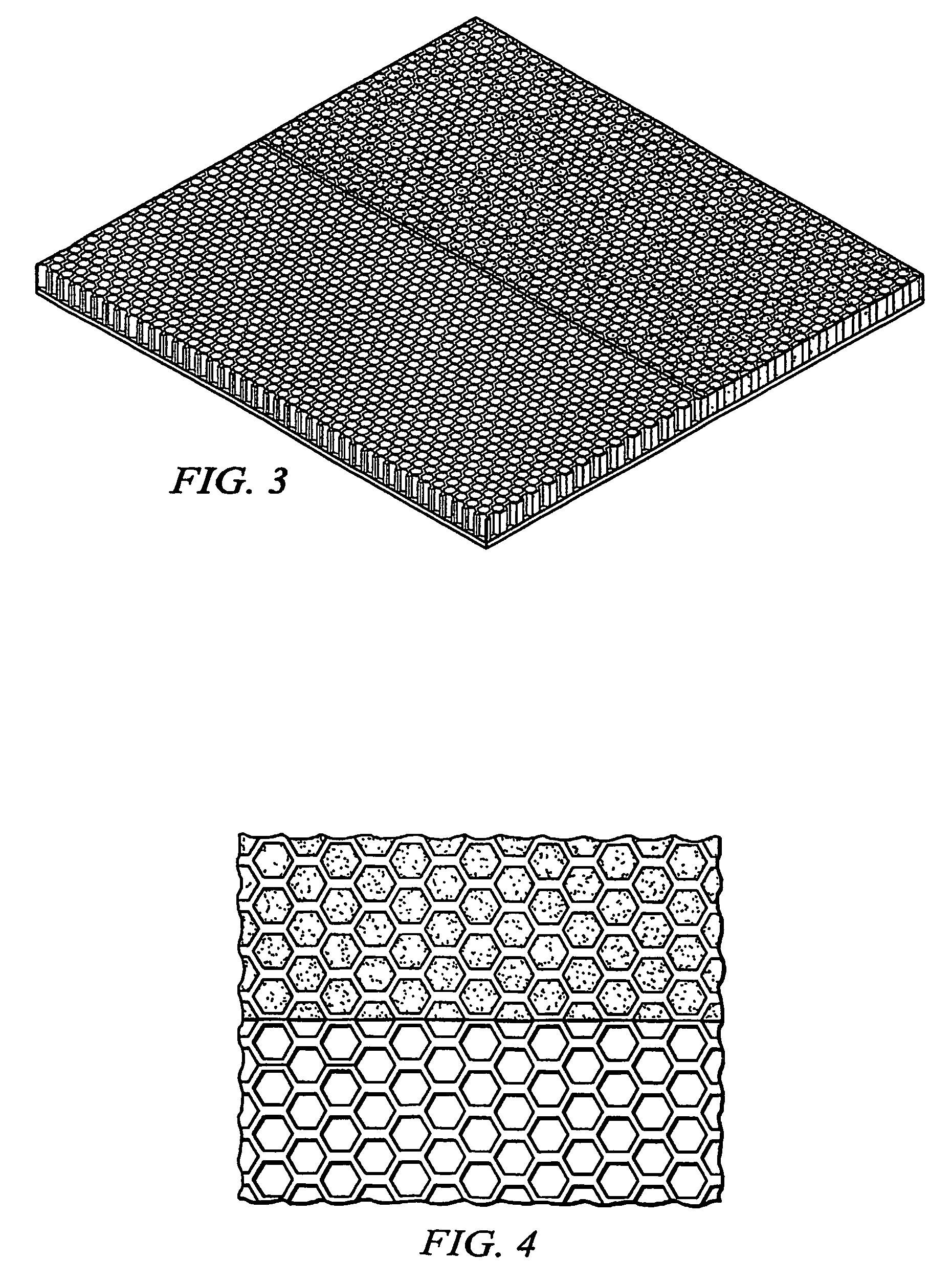
[0030]FIG. 1 is a perspective view of a radar-absorbing panel having a honeycomb structure and a lower skin assembly in which the individual cells of the honeycomb structure are fully filled with an aerogel in accordance with one embodiment of the present invention. FIG. 2 is a close-up perspective view of the honeycomb structure and lower skin assembly of FIG. 1. As seen in FIGS. 1 and 2, the honeycomb structure is made of an array of individual cells. The cells preferably have a hexagonal cross-sectional area; however, it should be understood that the individ...


PUM

PropertyMeasurementUnit
structureaaaaaaaaaa
cross-sectional shapeaaaaaaaaaa
physical propertiesaaaaaaaaaa

Abstract

The present invention provides a lightweight structure for simultaneously providing a reduced infrared and radar signature, while adding little or no weight to a vehicle. As such, the present invention allows for substantial improvements over prior systems. An example of the type of vehicle able to make use of the present invention is a military helicopter, but there is nothing within the spirit and scope of the present invention limiting it to any particular vehicle. The teachings of the present invention are useful with any vehicle for which a reduction in infrared emissions and microwave reflections is desired.

Description

TECHNICAL FIELD[0001]The present invention relates generally to methods of reducing the infrared and radar signature of a vehicle, specifically to the use of insulative and absorptive materials to reduce the amount of infrared radiation being emitted, and the radar signals being reflected, from certain aspects of the vehicle.DESCRIPTION OF THE PRIOR ART[0002]Vehicles involved in military operations have a need to reduce their visibility to opposing forces. This need exists for all methods modern military forces use to detect and target enemies. Examples of such methods include visual detection, audio detection, active and passive radar, and infrared detection. This need to a void detection is especially critical for aircraft, such as airplanes and helicopters, which have a high likelihood of being targeted by enemy air and ground forces using any and all of the above detection methods.[0003]To the end of reducing the infrared signature of aircraft, a number of methods have been deve...

Claims


Application Information

Patent Timeline
Patent Type & Authority Patents(United States)
IPC IPC(8): B32B3/12E04B1/16B29C70/08B32B5/16F41H3/00H01Q1/28H01Q17/00
CPCB29C70/086B32B3/12B32B5/02B32B5/16B32B17/02B64D7/00F41H3/00H01Q1/286H01Q17/00H01Q17/008Y10T428/24149Y02T50/433Y10T428/236Y10T428/1234B29L2031/3005Y02T50/40B32B2307/304B32B2307/718B32B2605/18
Inventor RILEY, BRYAN A.SHEPHERD, ROBERT A.
Owner BELL HELICOPTER TEXTRON INC
Why Eureka
Eureka Blog
Learn More