
Connector and a connector assembly

a technology of connectors and connector assemblies, which is applied in the direction of coupling device connections, securing/insulating coupling contact members, electrical devices, etc., can solve the problems of inadvertent separation of housings, and achieve high connection reliability, good locking strength, and balanced manner

Inactive Publication Date: 2008-07-08
SUMITOMO WIRING SYST LTD
View PDF5 Cites 15 Cited by
  • Summary
  • Abstract
  • Description
  • Claims
  • Application Information

AI Technical Summary

Benefits of technology

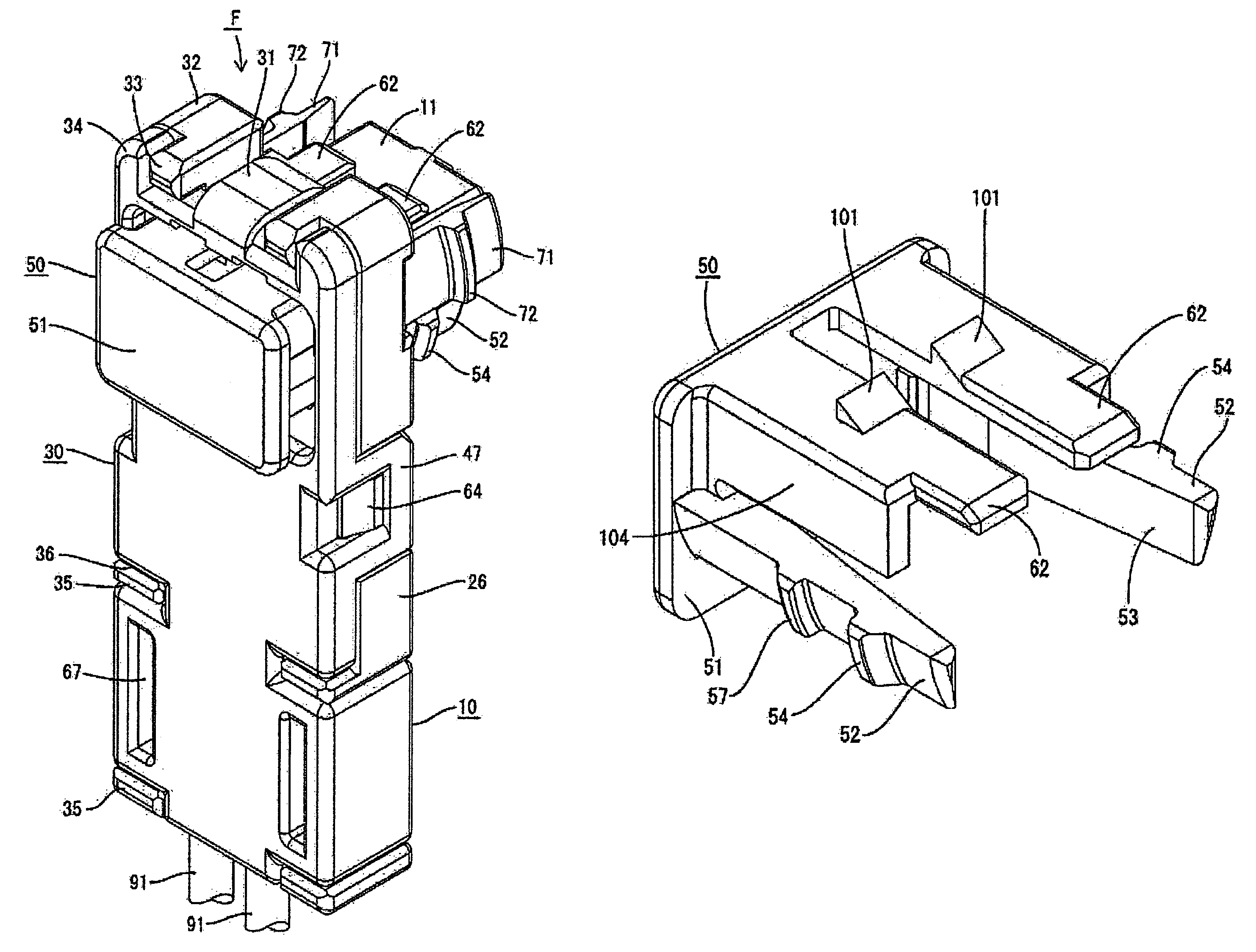
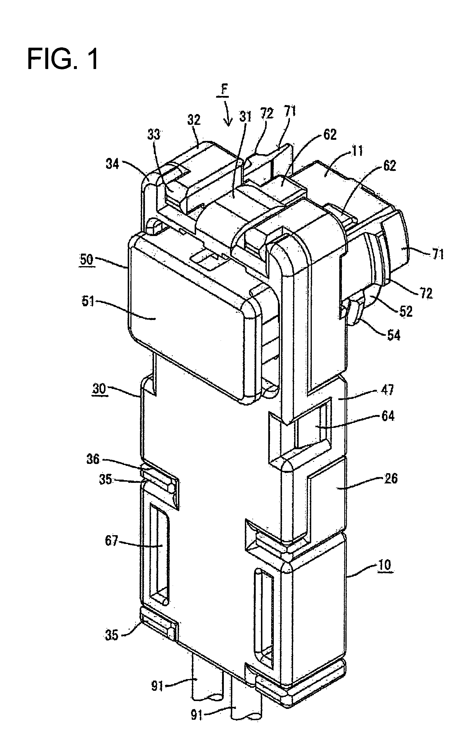
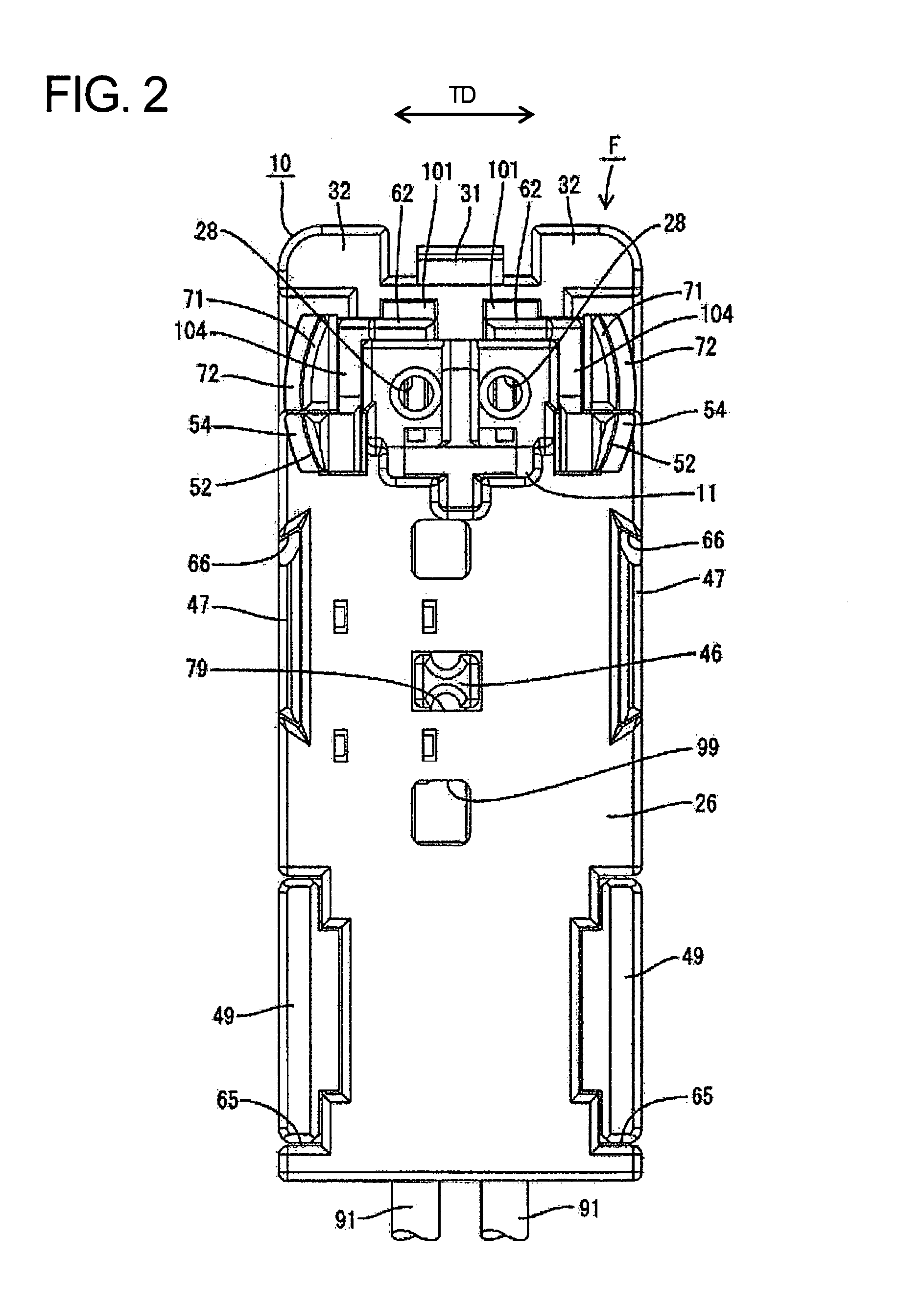
[0008]The push-in preventing portion and the retainer engage to prevent the detector from being pushed to the second position before the housings are connected properly. Thus, the detector cannot be pushed accidentally to the second position during transportation. On the other hand, the detector lock arm can deform to disengage the push-in preventing portion from the retainer when the two housings are connected properly so that the detector can be pushed to the second position. Thus, the connected state of the two housings can be detected depending on whether the detector can be moved.
[0010]The connected state of the housings is detected by pushing the detector in the pushing direction and is substantially parallel to the connecting direction. Thus, connection of the housings can be performed while the detector is being pushed, and it is not necessary to perform the connecting operation of the housings separately from the push-in operation of the detector.
[0015]The detector lock arms project from opposite sides of the operable portion and interlocking portions are on the mating housing in correspondence with the detector lock arms. Thus, the housings are locked in a well-balanced manner with good locking strength and high connection reliability.

Problems solved by technology

As a result, inadvertent separation of the housings is hindered.

Method used


Image

  • Connector and a connector assembly
  • Connector and a connector assembly
  • Connector and a connector assembly

Examples


Embodiment Construction

[0044]A connector assembly in accordance with the invention is described with reference to the accompanying drawings. The illustrated connector assembly is for an inflator, and hence constitutes part of a circuit of an airbag device. More particularly, the connector assembly has female and male connectors F, M connectable with each other. In the following description, ends of the connectors F, M that are to be connected are referred to as the front ends and reference is made to FIG. 1 concerning the vertical direction.

[0045]The male connector M is to be connected directly with the airbag device, and includes a male housing 80 formed from a synthetic resin and projecting integrally or unitarily from a wall of the device. The male housing 80 has a substantially round shape in front view, as shown in FIGS. 18 and 24, and has a substantially round outer frame 81. An inner frame 82 is fit into the outer frame 81 and has a forwardly open fitting recess 83 for receiving part of the mating ...


PUM


Abstract

A connector has female and male housings (10, 80) and a detector (50) that can move from a preventing position to a locking position on the female housing (10). Preventing portions (57) of the detector (50) engage retainers (59) of the female housing (10) if the detector (50) is pushed towards the locking position before the housings (10, 80) are connected. Detector lock arms (52) slide in contact with interfering portions (89) of the male housing (80) and deform if the detector (50) is pushed towards the locking position when the housings (10, 80) are connected. Thus, the preventing portions (57) separate from the retainers (59) and the detector (50) can move to the locking position as the detector lock arms (52) deform. The detector lock arms (52) restore and engage interlocking portions (88) of the male housing (80) as the detector (50) reaches the locking position.

Description

BACKGROUND OF THE INVENTION[0001]1. Field of the Invention[0002]The invention relates to a connector and to a corresponding connector assembly.[0003]2. Description of the Related Art[0004]U.S. Pat. No. 6,102,732 discloses a connector with two housings that are connectable with each other and a detector assembled into one housing to detect a connected state of the housings. A retainer is mounted in one housing and has a resiliently deformable lock arm to lock the housings together. A detecting piece of the detector is insertable into a deformation area of the lock arm. The lock arm remains deformed when the two housings are connected only partly. As a result, the detecting piece interferes with the lock arm and restricts a pushing movement of the detector. On the other hand, the lock arm restores resiliently to its natural state and opens a moving path for the detecting piece, when the housings are connected properly, thereby permitting the detector to be pushed. Thus, the connected ...

Claims


Application Information

Patent Timeline
Patent Type & Authority Patents(United States)
IPC IPC(8): H01R3/00
CPCH01R13/641H01R13/639H01R13/42
Inventor NAKAMURA, HIDETO
Owner SUMITOMO WIRING SYST LTD
Learn More