
High resolution projectile based targeting system

a projectile and high-resolution technology, applied in the field of high-resolution projectile based targeting systems, can solve the problems of complex processing of the return signal rpb>1/b>, prior art does not teach an ideal projectile for this use, and prior art does not address this problem, so as to achieve accurate determination of the instantaneous position of an underwater object, the effect of minimizing the effect of single projectile dispersion

Inactive Publication Date: 2008-07-01
THE GOVERNMENT OF THE UNITED STATES OF AMERICA AS REPRESENTED BY THE SEC OF THE NAVY NAVAL RES LAB WASHINGTON
View PDF25 Cites 3 Cited by
  • Summary
  • Abstract
  • Description
  • Claims
  • Application Information

AI Technical Summary

Benefits of technology

"The invention is a system for targeting underwater objects using a gun terminal with multiple waterproof breeches. The gun terminal launches noise generating projectiles in a pattern to detect and process the noise generated by the projectiles. The projectiles have a void region connected to the outer surface by a passage, which causes the void region to resonate at a noise generating frequency. The system can accurately determine the position of an underwater object and minimize the effects of single projectile dispersion."

Problems solved by technology

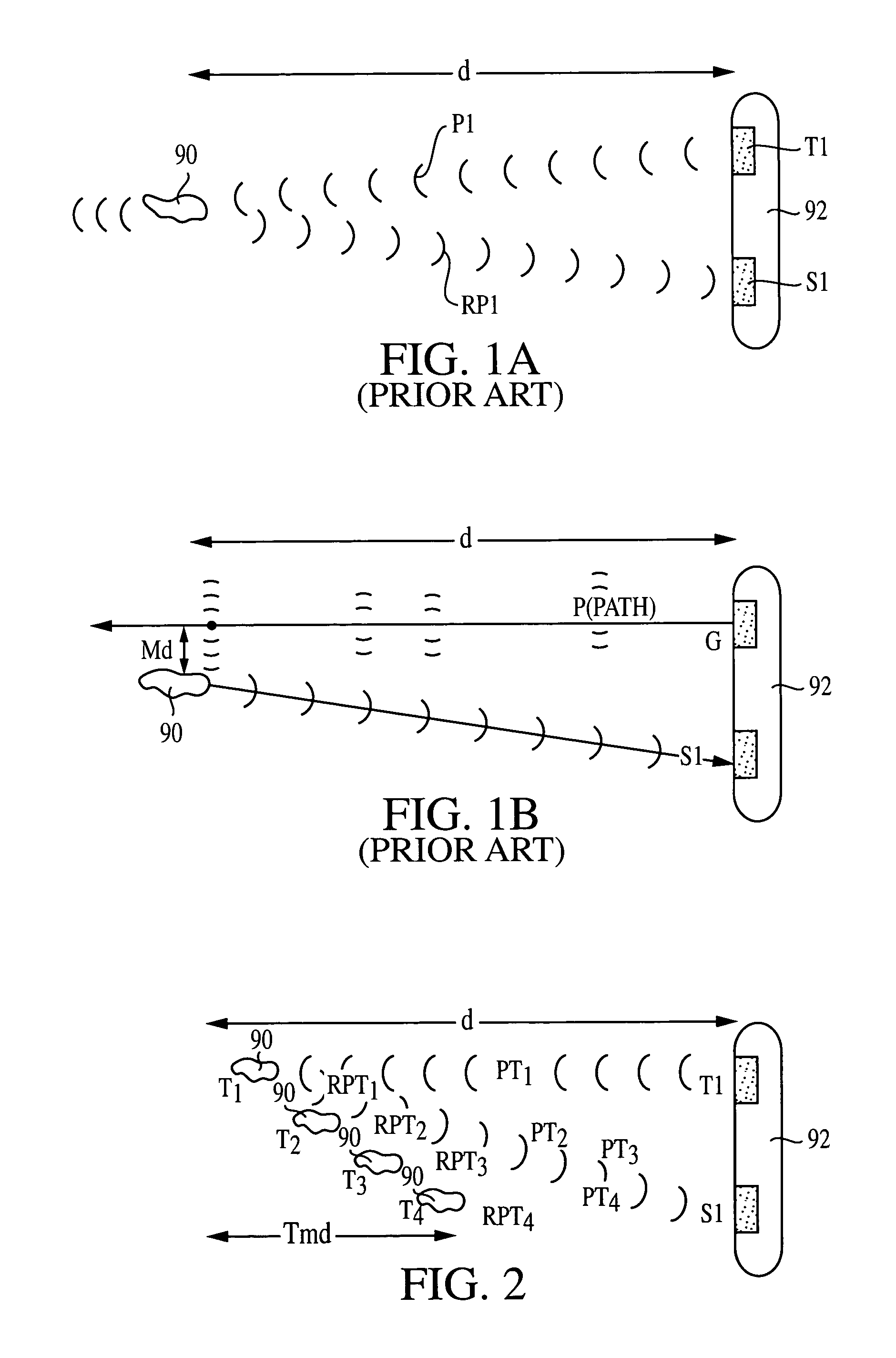
The processing of the return signal RP1 may be complicated by a number of factors such as bending of acoustic waves in thermal or salinity gradients, multiple target reflection and the like.
The prior art does not teach an ideal projectile for this use.
The distance the object migrates (Tmd) during that time in comparison to the initial standoff distance d is an important source of error in the understanding of the object's true position and track.
The prior art does not address this problem.

Method used


Image

  • High resolution projectile based targeting system
  • High resolution projectile based targeting system
  • High resolution projectile based targeting system

Examples


Embodiment Construction

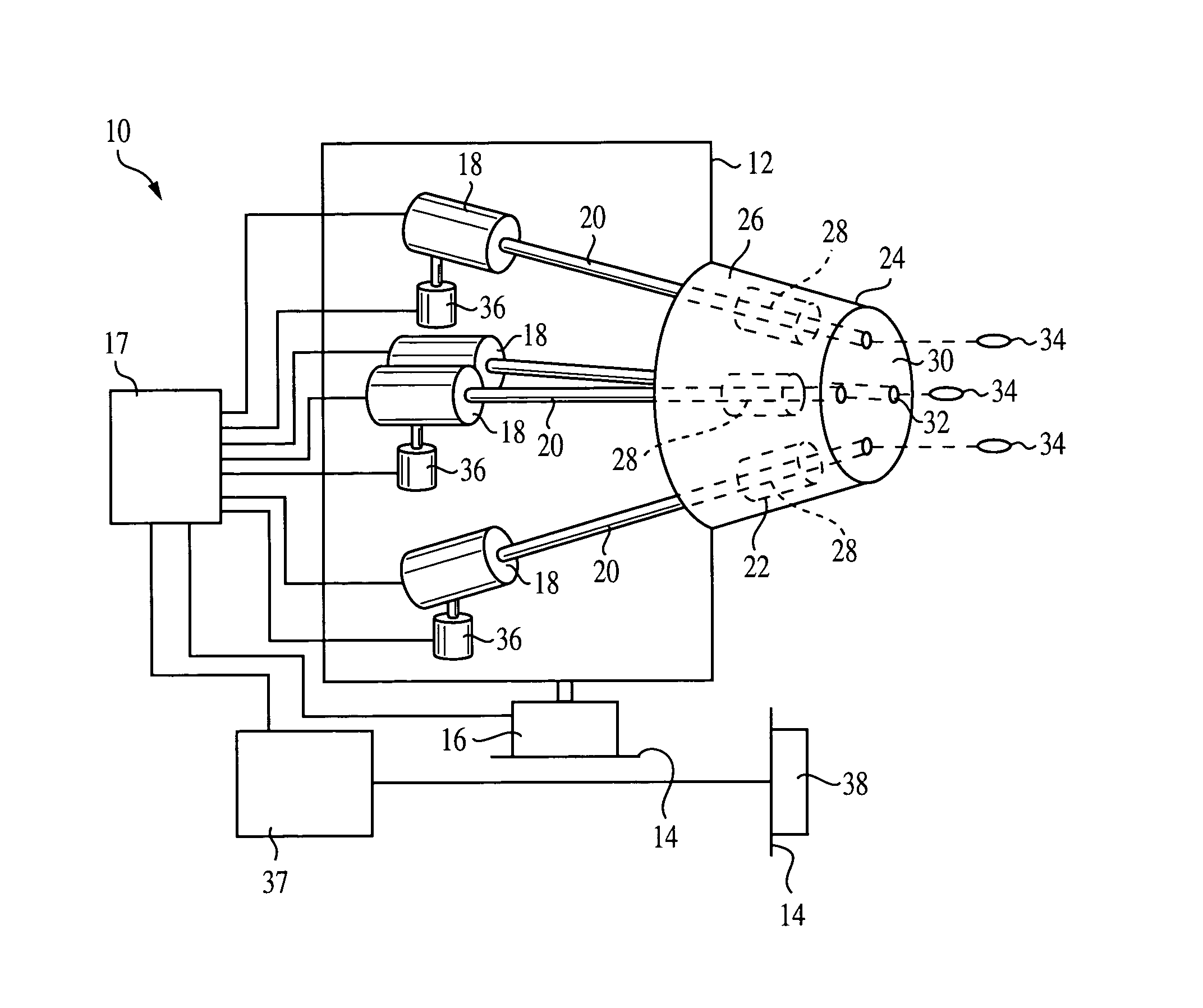
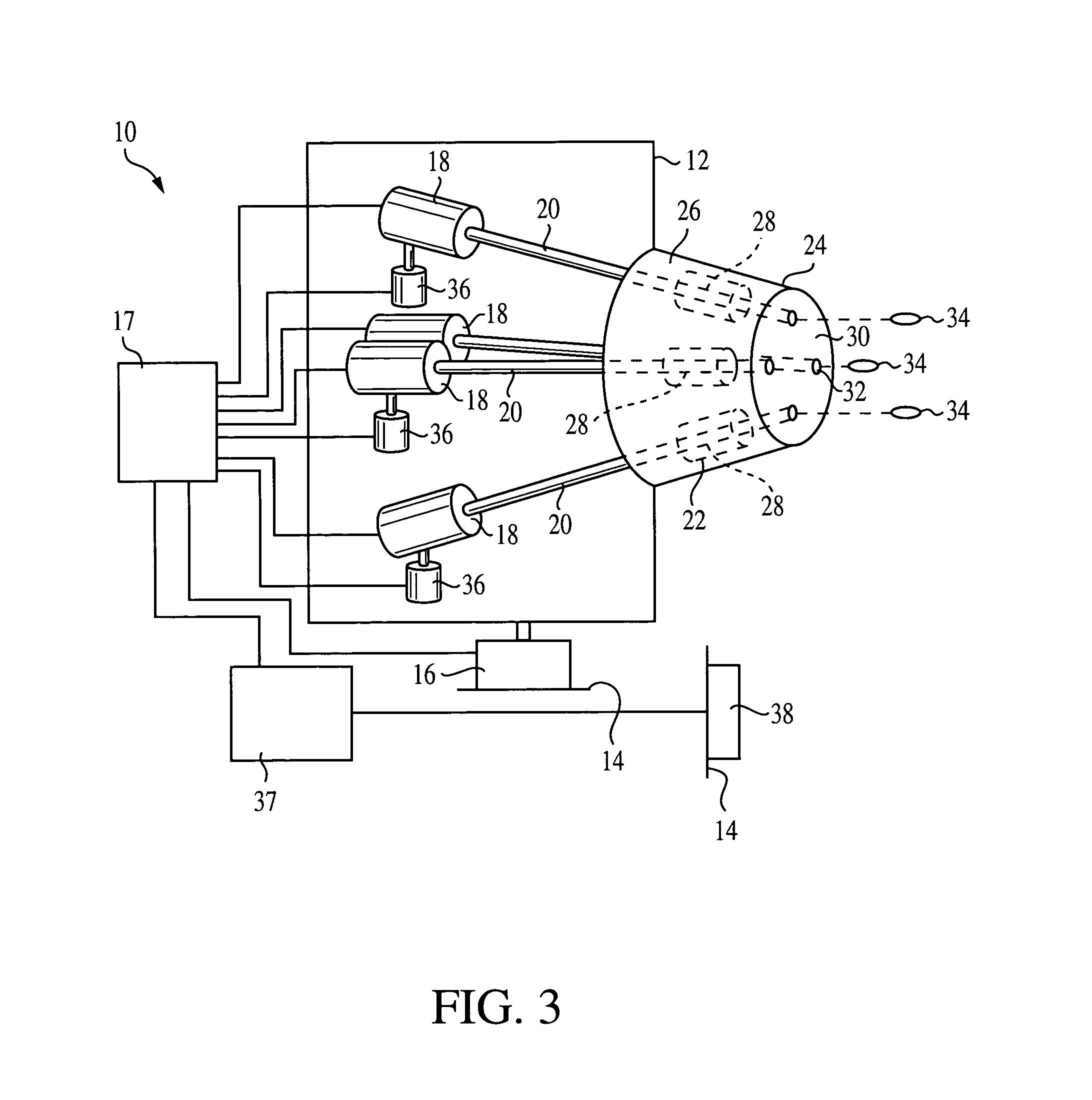
[0036]In general, the present invention is directed to a high resolution projectile based targeting system. More specifically, and referring first to FIG. 3 of the present invention, there is shown a gun system 10 used in the novel projectile targeting system of the present invention.

[0037]FIG. 3 shows a gun system 10 of the current invention. In system 10, a gun terminal 12 is joined to an underwater platform 14 by a trainable mounting fixture 16. A fire control system 17 is joined to trainable mounting fixture 16 and to a breech 18 associated with each gun. A gun barrel 20 is joined at its proximate end to each breech 18. The distal end of each gun barrel 20 is joined to a muzzle assembly 22. Muzzle assembly 22 includes a housing 24 having a gas deceleration area 26 defined therein. A sabot separator 28 associated with each gun is also located within deceleration area 26. The forward face 30 of muzzle assembly 22 has sealable apertures 32 formed therein for each gun. Muzzle assemb...


PUM


Abstract

A projectile based targeting system for underwater objects includes a trainable gun terminal mounted in a waterproof housing. The gun terminal includes plural gun barrels terminating in waterproof breeches. Noise generating projectiles are launched from the gun barrels, and a fire control system selectively fires the projectiles from each of the plural gun barrels in a noise pattern. A host controller detects and processes noise generated by a launched pattern of the noise generating projectiles to give information about the objects. The projectiles each include a void region connected to an outer surface of the projectile by a hole formed in a neck of the projectile. Launching of the projectile creates a vaporous cavity around the projectile and thus the hole, thereby causing the void region to resonate at a noise generating frequency.

Description

STATEMENT OF GOVERNMENT INTEREST[0001]The invention described herein may be manufactured and used by or for the Government of the United States of America for governmental purposes without the payment of any royalties thereon or therefor.BACKGROUND OF THE INVENTION[0002](1) Field of the Invention[0003]This invention generally relates to a system and apparatus to identify a position and near instantaneous track of an underwater object moving at any subsonic speed.[0004]More particularly, the invention relates to a system and apparatus as described in which the position of the underwater object is determined by a reflection of a radiated sound field from at least one projectile interacting with the underwater object. The system consists of a multi-barreled gun that discharges a multiplicity of projectiles in a predetermined time sequence and / or pattern. The projectiles themselves are designed to travel at a significant range and are modified to produce a high amplitude narrow frequenc...

Claims


Application Information

Patent Timeline
Patent Type & Authority Patents(United States)
IPC IPC(8): F41F3/10F42B15/20
CPCF41A21/26F41F3/07F41F3/10F41G3/06F41G3/14F42B15/22F41G9/008F42B12/36F42B14/06F42B15/20F41G3/142
Inventor KUKLINSKI, ROBERTGIESEKE, THOMAS J.
Owner THE GOVERNMENT OF THE UNITED STATES OF AMERICA AS REPRESENTED BY THE SEC OF THE NAVY NAVAL RES LAB WASHINGTON
Learn More