
Conduit connector assembly

a connector and assembly technology, applied in the direction of connection contact member materials, coupling device connections, manufacturing tools, etc., can solve the problems of devices that do not enable the armor cable to be attached to the body, and devices that do not meet current performance standards

Active Publication Date: 2008-06-24
HUBBELL INC
View PDF19 Cites 63 Cited by
  • Summary
  • Abstract
  • Description
  • Claims
  • Application Information

AI Technical Summary

Benefits of technology

The present invention is a connector assembly for connecting an electrical cable to an electrical box. The assembly includes a body, a grommet, and a spring clip. The spring clip is pre-attached to the cable before transportation to the work site, making assembly easier. The connector assembly is simple to manufacture and assemble, and can be easily incorporated into existing connector assemblies. The spring clip has hooks that engage with the inner edge of the opening in the electrical box to securely attach the connector to the box. The spring clip applies a gripping force to the cable, keeping it in place during transportation. The invention provides a convenient and efficient solution for connecting electrical cables to electrical boxes.

Problems solved by technology

These devices do not enable the armor cable to be attached to the body before installation into the electrical box.
While this connector device has performed with satisfaction over the years and has met objectives it was originally designed to achieve, the device does not meet current performance standards.

Method used


Image

  • Conduit connector assembly
  • Conduit connector assembly
  • Conduit connector assembly

Examples


Embodiment Construction

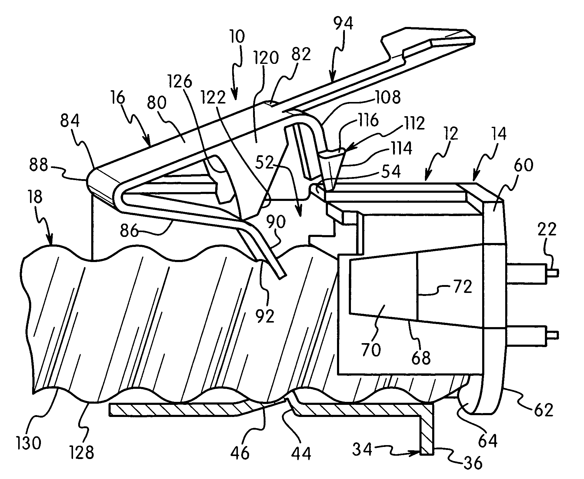
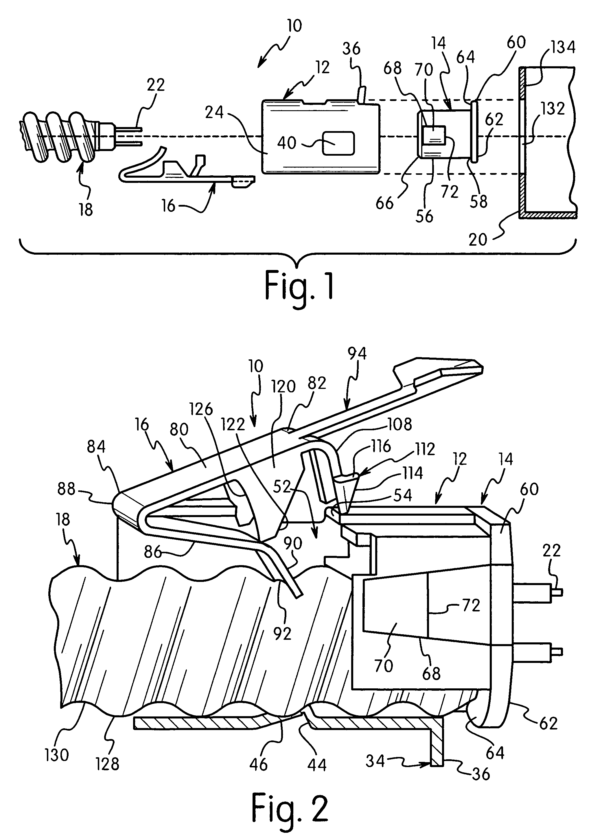
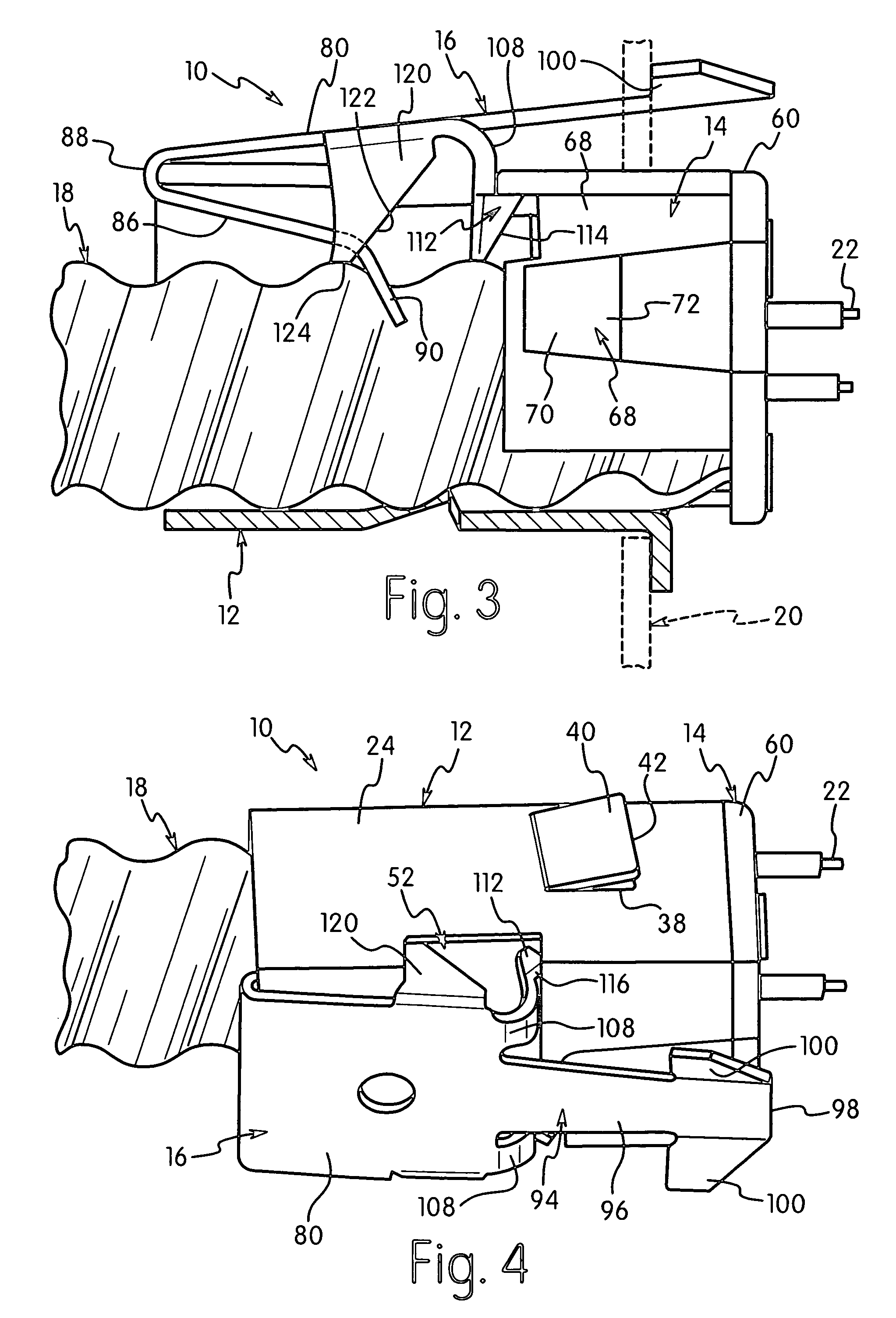
[0036]The present invention is directed to a conduit connector assembly for coupling a conduit to an electrical box. The invention is particularly directed to a conduit assembly that is able to couple an electrical conduit to a body of the assembly prior to coupling to an electrical box.

[0037]The assembly of the invention provides a structure that enables the conduit to be connected to the connector assembly so the connector is retained on the end of the conduit before assembly with the electrical box. The assembly allows pre-assembly of the conduit to the connector assembly to simplify the assembly at the work site. The conduit connector assembly of the invention basically includes a body, a grommet and a spring clip. The spring clip is attached to the body to grip the conduit to the body and to attach the body to an electrical box. The conduit is typically a spirally wound, corrugated armor cable as known in the art.

[0038]Referring to the drawings the conduit connector assembly 10...


PUM


Abstract

A conduit connector assembly which receives an end of a conduit carrying electrical wires includes a body, a grommet and a spring clip. The grommet and the spring clip are each mounted to the body. The spring clip is disposed within an interior bore of the fitting body and has a resiliently flexible body and a leg having a gripping end portion. The grip end has a substantially scalloped configuration for gripping and fitting partially about the conduit so as to center the grip end of the spring clip body on the conduit. The spring clip also includes a latching member to couple with the body to hold the spring clip in position and apply a biasing tension of the gripping end of the leg against the conduit. The grip end having the scalloped configuration is in the form of an arcuate concave-shaped edge surface on the gripping end portion of the body. The grip end of the spring clip body makes line contact with an inner convolution on an exterior of the conduit and makes at least a single point contact with an outer convolution on the exterior of the conduit. The grip end may be disposed at a predetermined angle for matching a predetermined pitch angle of the convolutions on the exterior of the conduit and thereby make line contact with the inner convolution on the exterior of the conduit and make a pair of point contacts with the outer convolution on the exterior of the conduit.

Description

FIELD OF THE INVENTION[0001]The present invention is directed to a conduit connector assembly for connecting an electrical conduit to an electrical box. More particularly the invention is directed to a conduit connector assembly for coupling to an armored cable prior to connecting to an electrical box.BACKGROUND OF THE INVENTION[0002]Electrical wiring is connected to an electrical box which supports various electrical devices such as switches and electrical receptacles. The wiring in some environments includes an armor cable wound around the wiring to protect the wiring. The armor cable must then be coupled to the electrical box. A variety of coupling devices have been produced for connecting the armor cable or conduit to the electrical box.[0003]Electrical wiring is used for connecting electrical power lines and electrical outlets in order to provide access to electrical power in residential and commercial buildings. Electrical junction boxes are provided in the buildings to receiv...

Claims


Application Information

Patent Timeline
Patent Type & Authority Patents(United States)
IPC IPC(8): H02G3/18
CPCH02G3/0691Y10T16/05
Inventor JOHNSON, STEVEN J.
Owner HUBBELL INC
Learn More