
High throughput processing system and method of using

Inactive Publication Date: 2008-06-24
NOVARTIS AG
View PDF111 Cites 159 Cited by
  • Summary
  • Abstract
  • Description
  • Claims
  • Application Information

AI Technical Summary

Benefits of technology

[0012]In some embodiments, the sample holders comprise one or more lids. An example lid of the invention comprises a cover having a top surface, a bottom surface, and a side. An alignment protrusion extends from the side of the cover, e.g., positioned to cooperate with an alignment member of the multiwell plate. In addition, a sealing perimeter is positioned on the bottom surface of the cover. The alignment protrusion facilitates aligning the lid to the plate so that a seal is compressibly received between the sealing perimeter and a sealing surface of the multiwell plate. The lids are, in some embodiments, constructed of a heavy material such as stainless steel. A de-lidding station is also optionally incorporated into the systems of the invention, at which station a lid is removed from a sample holder.

Problems solved by technology

High throughput automated systems typically involve rapid, repetitive manipulations of individual elements.
One deficiency in existing technology is that as processing throughputs increase there is a degradation of reliability.
This system, however, suffers from a lack of flexibility.
The plates must proceed in a linear fashion along the entire track, thus limiting throughput.
Further, once the rack, workstation, and cooperating transports are in place, it is difficult to reconfigure the system.
In addition, samples in the specimen plates are subjected to an open and unprotected environment for an extended period of time as the plates move from the sample racks to the workstations.
Thus, the samples may become impermissibly dry or contaminated.
In such a manner, the system is cumbersome to operate in a process having many steps and using several different workstations.
Disadvantageously, current high throughput processing systems are limited to unidirectional workflow and inflexible testing regimes.
Current systems do not allow for a sample to proceed, for example, from an assaying step, to a dispensing step, and then back to the previous assaying step.
The demand for high throughput systems with decreased reconfiguration needs that are prone to less contamination and can process samples multi-directionally within the system is as yet unmet.

Method used


Image

  • High throughput processing system and method of using
  • High throughput processing system and method of using
  • High throughput processing system and method of using

Examples


Embodiment Construction

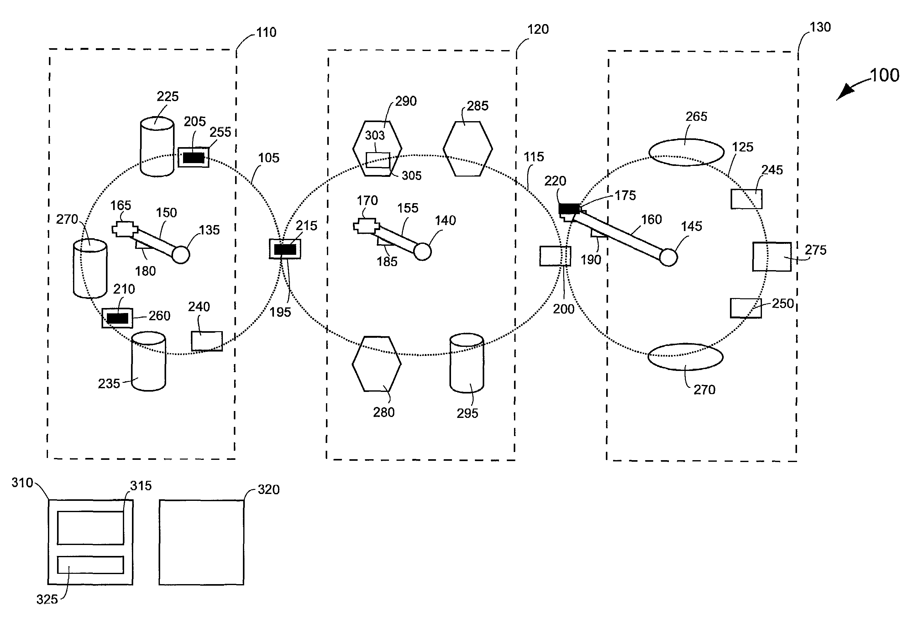
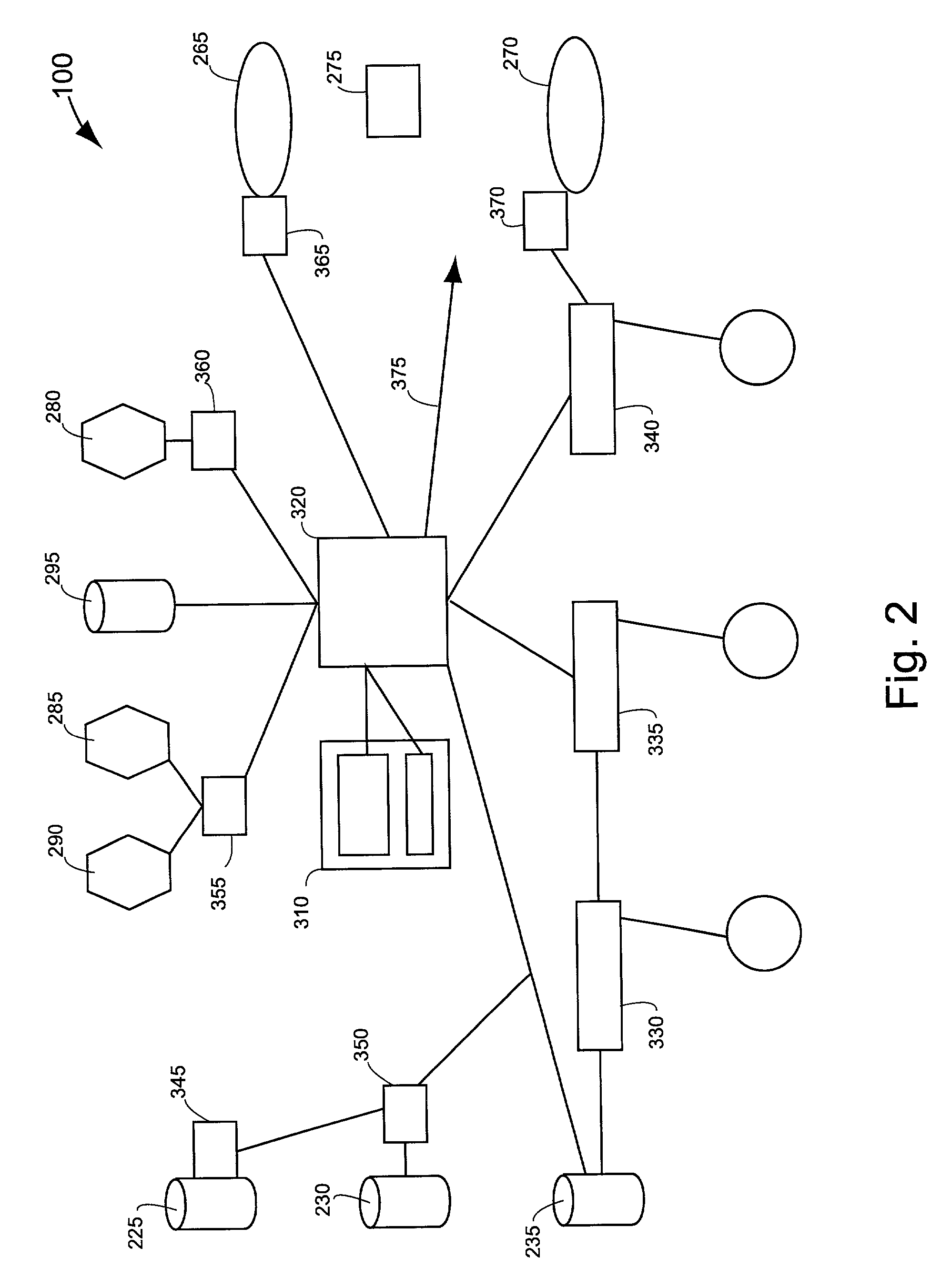
[0046]The present invention provides flexible, robust, accurate, and reliable systems and methods for high throughput processing, e.g., for screening large numbers of samples. The present invention alleviates to a great extent the disadvantages of known systems and methods for screening, analysis, and assembly. For example, the present system provides multi-directional and non-linear transport between multiple devices. Accordingly, the present invention improves the reliability, efficiency, and flexibility of processes such as high throughput screening and other methods requiring repetitive manipulations of many individual elements. In addition, the present invention also provides accurate and quick assembly of multi-element devices such as medical devices, testing devices, and / or electronic devices.

[0047]A typical system of the invention comprises a plurality of rotational robots, each of which is associated with a work perimeter. Within each work perimeter are a number of devices,...


PUM

PropertyMeasurementUnit
Timeaaaaaaaaaa
Forceaaaaaaaaaa
Volumeaaaaaaaaaa

Abstract

Briefly, the present invention provides a system and method for high throughput processing using sample holders. The system has a plurality of work perimeters, with a rotational robot preferably associated with each work perimeter. At least one transfer station area is provided between adjacent work perimeters to facilitate robotic transfer of sample holders from one work perimeter to another area. Each work perimeter typically includes a plurality of defined station locations, with each station location positioned to be accessible by the robot associated with that area. In addition, each station location is typically configured to receive a device, such as an automated instrument or a holding nest. Device components are arranged at selected station locations according to specific application requirements to provide a flexible, robust, reliable, and accurate high throughput processing system.

Description

CROSS REFERENCE TO RELATED APPLICATIONS[0001]Pursuant to 35 U.S.C. §§ 119, 120, and any other applicable statute or rule, the present application claims benefit of and priority to U.S. Patent Application Ser. No. 60 / 240,361, filed Oct. 13, 2000, entitled “High Throughput Processing System and Methods of Using,” and the PCT application entitled “High Throughput Processing System and Methods of Using,” filed Oct. 15, 2001, PCT / US01 / 32454, the disclosures of which are incorporated herein by reference in their entirety for all purposes.COPYRIGHT NOTIFICATION[0002]Pursuant to 37 C.F.R. 1.71(e), a portion of this patent document contains material which is subject to copyright protection. The copyright owner has no objection to the facsimile reproduction by anyone of the patent document or the patent disclosure, as it appears in the Patent and Trademark Office patent file or records, but otherwise reserves all copyright rights whatsoever.BACKGROUND OF THE INVENTION[0003]Automated processin...

Claims


Application Information

Patent Timeline
IPC IPC(8): G01N35/10B01L3/02B25J15/00G01N21/01G01N33/50G01N33/53B01L9/00C12N15/09C12Q1/02C12Q1/37C12Q1/42C12Q1/48C12Q1/68G01N15/10G01N33/566G01N35/00G01N35/02G01N35/04G01N37/00
CPCB01L9/523G01N35/0099G01N35/04B01J2219/00587Y10T436/2575B01J2219/00691B01J2219/00707B01J2219/0072B01L2300/0829B01L2300/0893G01N35/025G01N35/026G01N35/028G01N35/1074G01N2015/1006G01N2035/00306G01N2035/00366G01N2035/0405G01N2035/0427G01N2035/1037G01N2500/10G01N2500/20Y10T436/114165B01J2219/00689Y02A50/30
Inventor BUROW, KRISTINA MARIECALDWELL, JEREMY S.DOWNS, ROBERT CHARLESLESLEY, SCOTT ALLANMAINQUIST, JAMES KEVINMEYER, ANDREW J.SIPES, DANIEL G.WESELAK, MARK RICHARD
Owner NOVARTIS AG
Learn More