
Device and method for the continuous non-invasive measurement of blood pressure

a non-invasive and continuous technology, applied in the field of continuous, non-invasive measurement of blood pressure, can solve the problems of false indication of drop or rise in blood pressure, user's inability to decide whether an observed change in blood pressure or a amplitude of blood pressur

Inactive Publication Date: 2008-06-24
CNSYST MEDIZINTECHN
View PDF12 Cites 54 Cited by
  • Summary
  • Abstract
  • Description
  • Claims
  • Application Information

AI Technical Summary

Benefits of technology

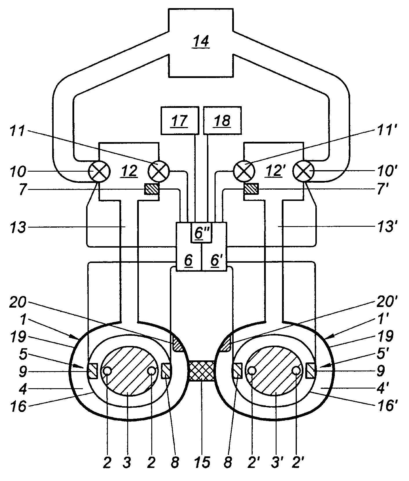
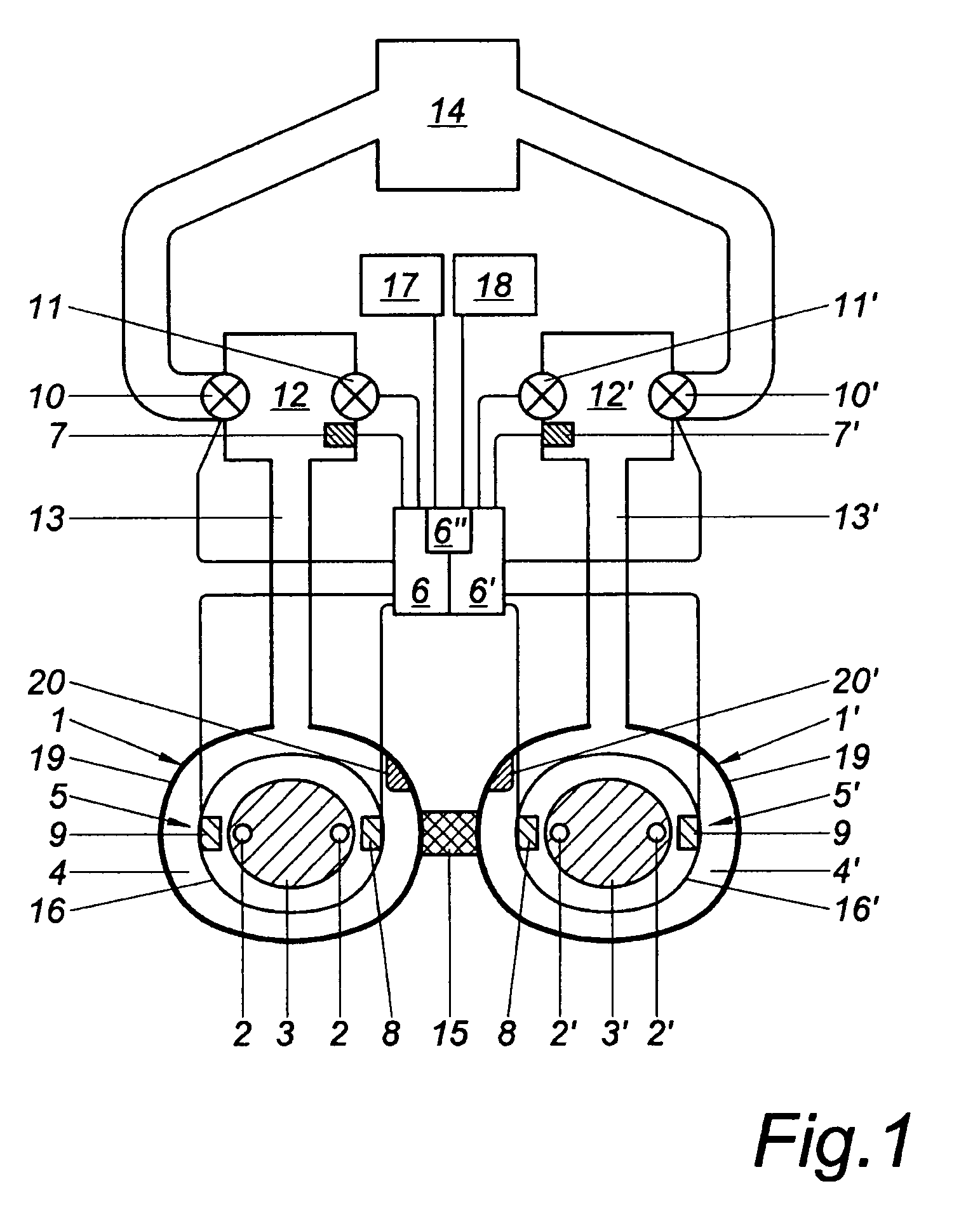
[0014]A device for implementation of the method of the invention is characterised in that the pressure measuring chamber of the second pressure cuff is configured as a reference pressure chamber which can be controlled simultaneously with and independently of the pressure measuring chamber of the first pressure cuff, and that the pressure measuring chamber of the first pressure cuff and the reference pressure chamber of the second pressure cuff each have separate inlet and outlet valves, with the pressure in the reference pressure chamber being controllable in accordance with a pre-selectable pressure function by means of a control unit. It is thus possible to obtain a measured pressure signal and a reference signal simultaneously.
[0015]The present invention thus avoids the disadvantages mentioned above by providing the possibility of simultaneously and continuously monitoring the closed-loop blood pressure measurement by means of a “watchdog” unit, i.e. the open-loop measurement in the reference chamber. To this end similarly or identically dimensioned or configured pressure chambers must be placed over arteries of similar or identical dimension. The double finger cuff described in WO 00 / 59369 A2 is particularly suitable for this purpose but has to be adapted for the needs of the present invention, primarily by providing the pressure measuring chamber of the first pressure cuff and the reference pressure chamber of the second pressure cuff each with separate inlet and outlet valves.
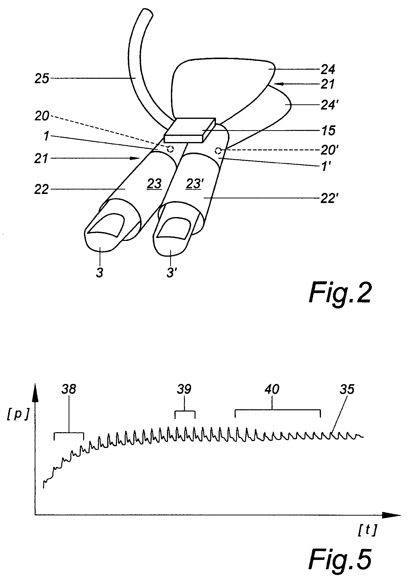
[0016]Although the pressure measuring chamber and the reference pressure chamber in principle may be placed over diverse arteries, for instance over the arteria temporalis and arteria radialis, it is of particular advantage—especially for long-time measurement—if both pressure cuffs are placed over neighbouring arteries, preferably those of two adjacent fingers of one hand. The other hand will thus be freely accessible for necessary intensive care purposes.
[0022]Due to the completely identical construction of the pressure chambers of the two pressure cuffs it is possible to operate the reference pressure chamber as pressure measuring chamber and the latter as reference pressure chamber either during predetermined periods of time or if the setpoint is lost. Thus the watchdog pressure chamber may at any time be switched to act as closed-loop pressure measuring chamber and vice versa. This arrangement also has the great advantage that the part of the body, e.g. the finger, which is used for closed-loop measurement, may repeatedly be changed either automatically or manually, without interrupting the recorded pulse curve. It is only necessary immediately before switch-over to use the last setpoint obtained in the reference pressure chamber to determine the setpoint for the closed-loop measurement and then to switch to closed-loop measurement of blood pressure on this finger, before closed-loop measurement on the other finger is ended. The other finger subsequently is used to find and monitor the setpoint.

Problems solved by technology

When the feedback loop is closed, the setpoint can no longer be checked properly.
It is therefore necessary in the known methods to intermittently interrupt the continuous measurement for readjustment of the setpoint, or the setpoint may be lost during measurement, which may result in false indication of a drop or rise in blood pressure.
Under these circumstances the user is unable to decide whether an observed change in blood pressure or blood pressure amplitude is caused by a physiological or pathological change of intra-arterial blood pressure or by a shift of the setpoint.
This has made the method unsuitable for application in intensive care units or in the operating theatre where it would be most urgently needed.
This should only be done, however, if planned, routine switching is carried out, but not if uncorrected setpoint shifts have previously occurred.

Method used


Image

  • Device and method for the continuous non-invasive measurement of blood pressure
  • Device and method for the continuous non-invasive measurement of blood pressure
  • Device and method for the continuous non-invasive measurement of blood pressure

Examples


Embodiment Construction

[0032]FIG. 1 shows a device for the continuous, non-invasive measurement of blood pressure, with at least one first pressure cuff 1, which can be attached to a first body part or body region 3 containing an artery 2, and which comprises an inflatable pressure measuring chamber 4 and a first plethysmographic sensor device 5, and where a control and adjusting unit 6 is provided, which controls the pressure in the pressure measuring chamber 4 by means of the measurement signal of the plethysmographic sensor device 5, in such a way that the amplitude of the plethysmographic measurement signal is minimized. The pressure measuring chamber 4 is connected with a least one pressure sensor 7 to obtain a pressure measuring signal. The device of the invention has a second pressure cuff 1′, which can be attached to a second body part or body region 3′ containing an artery 2′, and which comprises an inflatable reference pressure chamber 4′ (watchdog pressure chamber) of the same design as the pre...


PUM


Abstract

A method for the continuous non-invasive measurement of blood pressure includes at least one first pressure cuff and one second pressure cuff of comparable or identical size, each cuff including an inflatable pressure measuring chamber applicable to a first and a second body part or region containing an artery. The first pressure cuff has a first plethysmographic sensor connected to a regulating and control device used to regulate the pressure in a first pressure measuring chamber by means of a measuring signal of the plethysmographic sensor. The first pressure measuring chamber is connected to a pressure sensor in order to obtain a pressure measuring signal. The second pressure measuring chamber is a reference pressure chamber that can be regulated at the same time as the first pressure measuring chamber, independently therefrom, and can be regulated by the regulating and control device according to a pre-determinable pressure function.

Description

BACKGROUND OF THE INVENTIONFIELD OF THE INVENTION[0001]The invention relates to a method and device for continuous, non-invasive measurement of blood pressure based on the principle of the unloaded arterial wall, where on at least one first and one second body part or body region, each containing an artery of identical or comparable size, there is positioned one first and one second pressure cuff of identical or comparable size with one first and one second inflatable pressure measuring chamber, the pressure in the first pressure measuring chamber being controlled in dependence of the measurement signal of a plethysmographic sensor device in such a way that the amplitude of the plethysmographic measurement signal is minimized, and a pressure measurement signal being obtained from the first pressure measurement chamber.THE PRIOR ART[0002]In medical practice it is often necessary to measure continuously the blood pressure of living beings. Non-invasive measurement avoiding the punctur...

Claims


Application Information

Patent Timeline
IPC IPC(8): A61B5/02A61B5/022A61B5/0225
CPCA61B5/02241A61B5/02255A61B5/0295A61B5/6806
Inventor SKRABAL, FALKOFORTIN, JURGEN
Owner CNSYST MEDIZINTECHN
Learn More