Radio communication apparatus
a radio communication and apparatus technology, applied in the direction of substation equipment, broadcast system receiving, differential interacting antenna combinations, etc., can solve the problems that the radio communication environment remains to be bad fixedly, and the radio communication equipment cannot maintain the good status of radio communication
- Summary
- Abstract
- Description
- Claims
- Application Information
AI Technical Summary
Benefits of technology
Problems solved by technology
Method used
Image

Examples
embodiment 1
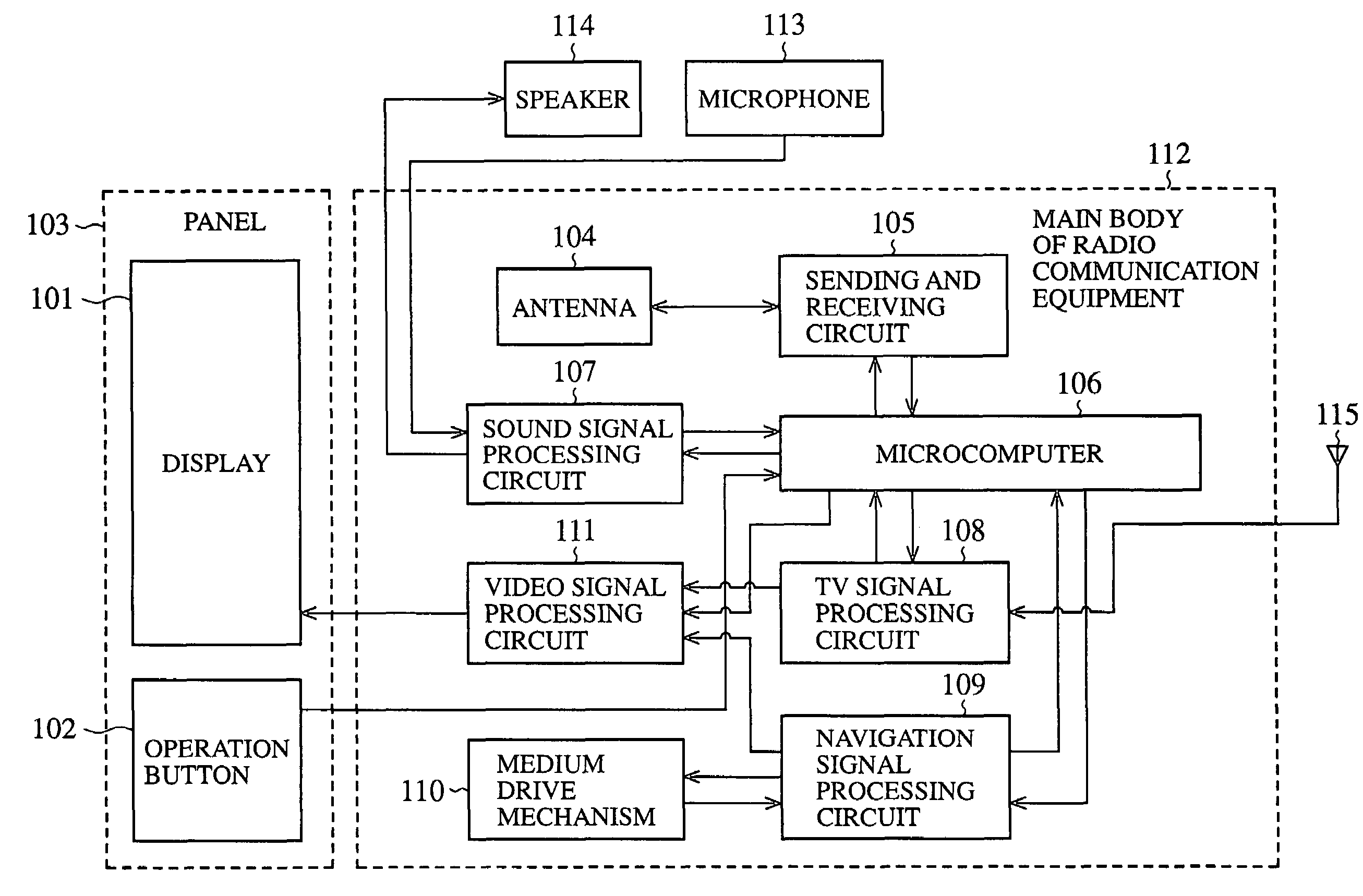
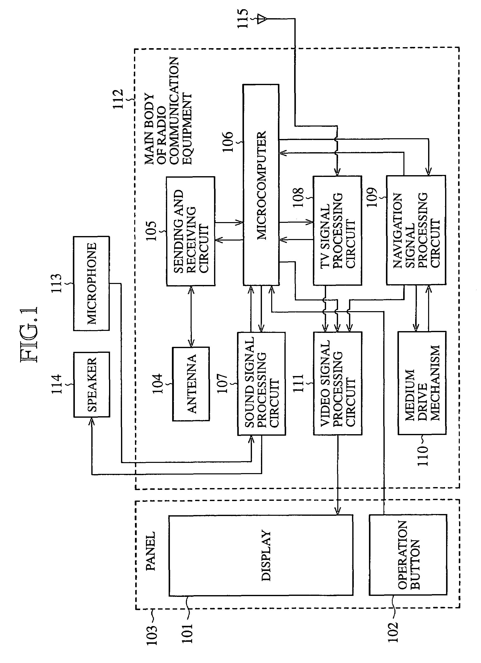
[0037]FIG. 3 is a functional block diagram showing the structure of radio communication equipment in accordance with embodiment 1 of the present invention, which is applied to a vehicle-mounted navigation apparatus, for example. In FIG. 3, reference numeral 1 denotes a display for displaying a map screen intended for vehicle navigation, a TV picture, or the like thereon, reference numeral 2 denotes an operation button for switching among various functions, reference numeral 4 denotes an antenna for sending and receiving electric waves through radio communications, reference numeral 3 denotes a panel in which the display 1, the operation button 2, and the antenna 4 are accommodated, reference numeral 5 denotes a sending and receiving circuit for encoding and decoding radio signals to be sent and received byway of the antenna 4, reference numeral 6 denotes a received level determining circuit (i.e., a reception status determining means) for measuring the received level of a received e...
embodiment 2
[0045]FIG. 5 is an explanatory drawing showing the structure of a main body 15 of radio communication equipment in which an antenna 4 for sending and receiving electric waves for radio communication is mounted. For example, an insertion opening 15a for cassette tapes and an insertion opening 15b for CDs are disposed in a front surface of the main body 15 of radio communication equipment. A lower edge of a panel 3 accommodating a display 1 in a frame 19 thereof is attached to the main body 15 of radio communication equipment by way of a hinge (not shown in the figure), for example, so that the panel 3 can cover the insertion openings 15a and 15b and can be opened and closed.
[0046]When the central direction of the directivity pattern of the antenna 4 for radio communication accommodated in the opening and closing panel 3 mounted on the main body 15 of radio communication equipment is oriented in a direction of the front of the main body 15, the directivity pattern roughly confronts mo...
embodiment 3
[0050]FIG. 6 is an explanatory drawing showing the structure of a main body 15 of radio communication equipment in which an antenna 4 for sending and receiving electric waves for radio communication is mounted. The main body 15 of radio communication equipment is the one that is provided as an extension of that in accordance with embodiment 2 shown in FIG. 5, and is provided with two antennas 4 built in a panel 3 and having directivity patterns whose central directions are different from each other. FIG. 6(a) is a state diagram showing the panel 3 which is closed, and FIG. 6(b) is a state diagram showing the panel 3 which is opened and inclined in a slightly-downward direction.
[0051]Either a method of selectively using one of the two antennas 4 with a higher received signal level or a method of using the two antennas 4 and combining the levels of signals received by the two antennas 4 can be adopted. Consequently, the radio communication equipment can finely adjust a tilting angle o...
PUM
 Abstract
Description
Claims
Application Information
 - Generate Ideas
- Intellectual Property
- Life Sciences
- Materials
- Tech Scout
- Unparalleled Data Quality
- Higher Quality Content
- 60% Fewer Hallucinations
Browse by: Latest US Patents, China's latest patents, Technical Efficacy Thesaurus, Application Domain, Technology Topic, Popular Technical Reports.
© 2025 PatSnap. All rights reserved.Legal|Privacy policy|Modern Slavery Act Transparency Statement|Sitemap|About US| Contact US: help@patsnap.com