
Methods for improving the performance of a detector

a detector and performance technology, applied in the field ofsignal processing, can solve the problems of limiting the manner in which the ccd is used in biological analysis, and achieve the effect of improving flexibility and improving the identification of the presen

Active Publication Date: 2008-06-17
APPL BIOSYSTEMS INC
View PDF1 Cites 3 Cited by
  • Summary
  • Abstract
  • Description
  • Claims
  • Application Information

AI Technical Summary

Benefits of technology

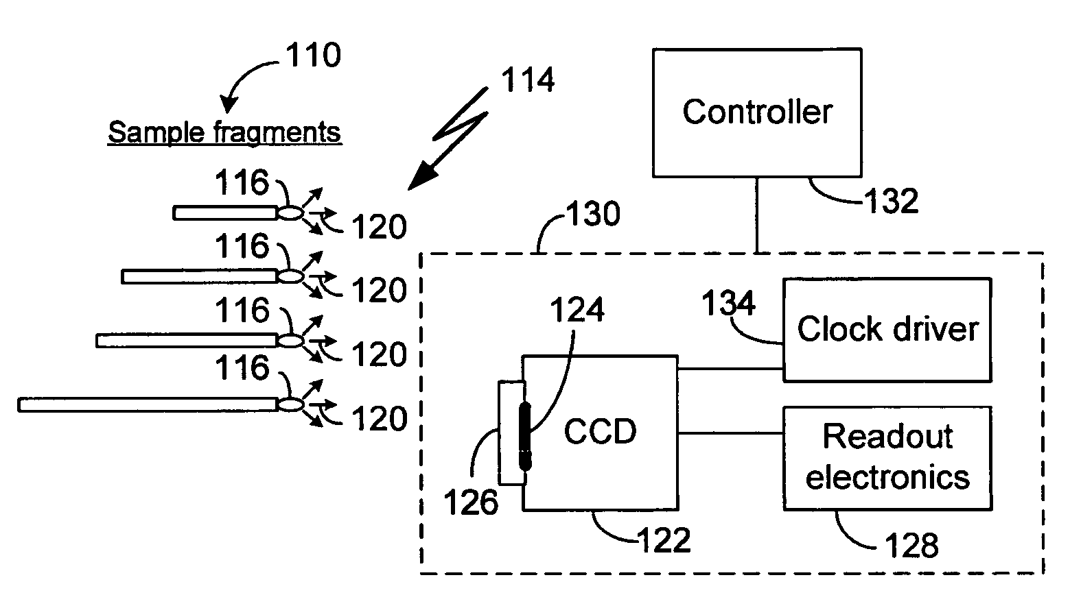
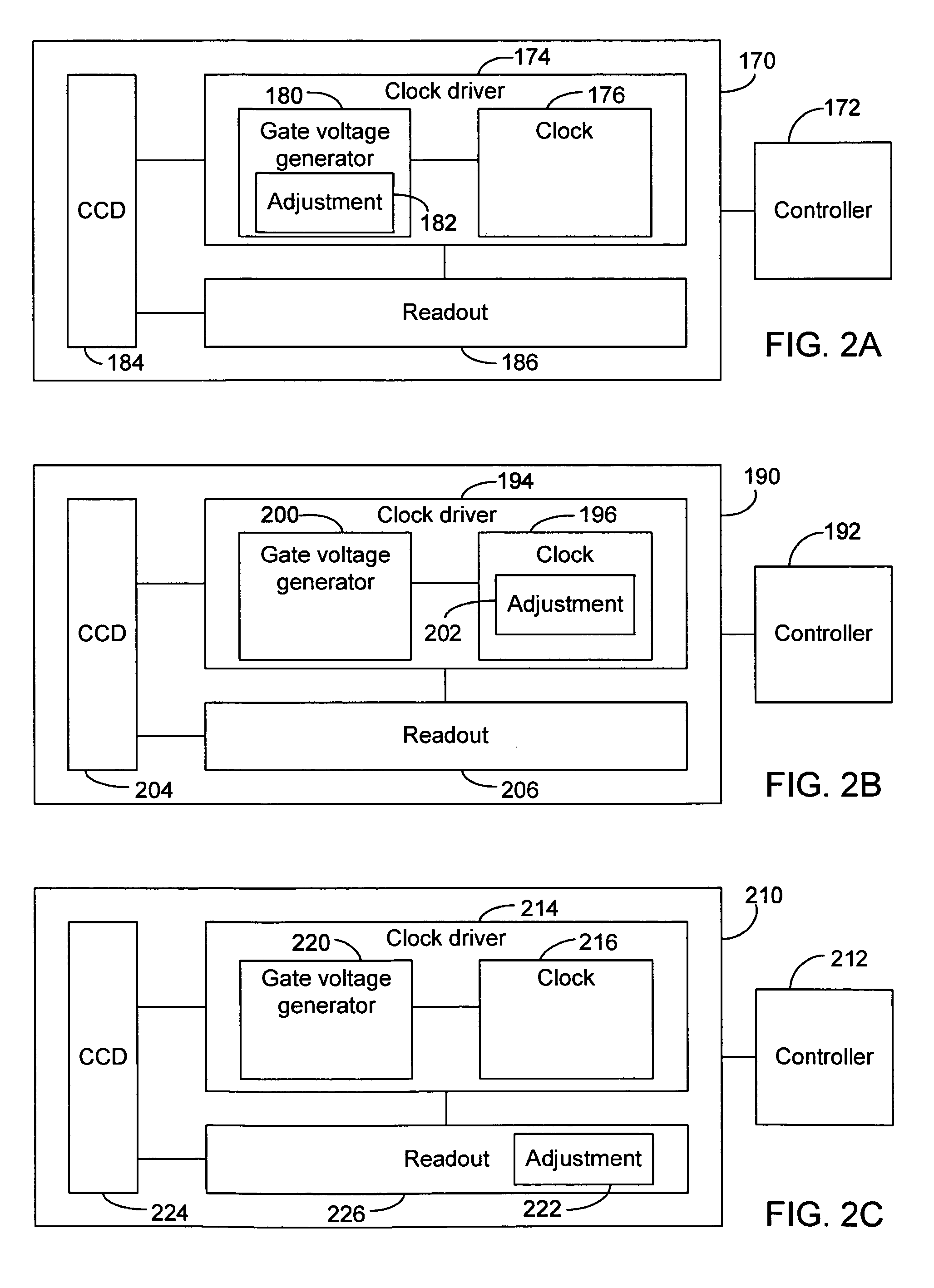
[0007]One aspect of the present teachings relates to a system for interrogating a sample using a probe array configured to be responsive to a plurality of particles. The probe array generates one or more identifiable signals following interaction with the sample particles. The sample composition is resolved, at least in part, by identifying the signals associated with each constituent probe of the array. The system comprises a segmented detector configured to detect at least a portion of the one or more identifiable signals associated with the constituent probes of the probe array. The position of each constituent probe and the signal arising therefrom are used to identify the presence or absence of particles contained within the sample. The segmented detector comprises a plurality of pixels adapted to collect charges generated in response to the one or more identifiable signals. The magnitude of the collected charge in a given pixel is representative of the intensity of the one or more identifiable signals impinging on the given pixel. The pixel is adapted to allow transferring of the collected charge by an application of one or more gate voltages to the pixel. The system further comprises a clock driver that provides the one or more gate voltages to the pixel. The manner in which the gate voltages are applied to the pixel affects the manner in which the collected charge is transferred from the pixel. The system further comprises a readout component that reads out the charges transferred out from the pixels to thereby yield an output signal corresponding to each pixel wherein the output signal is representative of the magnitude of the pixel's collected charge. The system further comprises a controller configured to control at least one of the clock driver and the readout component so as to allow selective adjustment of the manner in which the gate voltages is applied to the pixel or the manner in which the readout occurs. The controller being able to control the manner in which the detector operates facilitates an improved flexibility in which the system is configured for a given analysis application thereby providing an improved position information of the constituent probes of the probe array thereby allowing improved identification of the presence or absence of particles contained within the sample.
[0010]In certain embodiments, the readout component comprises an adjustment component that adjusts one or more parameters that affect the manner in which the readout occurs. In one embodiment, the adjustment component comprises a radio-frequency interference (RFI) filter configured to be controlled by the controller so as to adjust the manner in which it filters a clock signal from a clock. The adjustment of the filtering affects the manner in which reset gate signals reset a charge detector circuit of the readout component. In one embodiment, the filtering is adjusted so that the charge detector's reset time is reduced thereby increasing the rate at which the readout cycle operates.
[0013]Another aspect of the present teachings relates to a method for improving the performance of a segmented detector of a biological analysis system having an array of biological probes positioned on an analysis platform. Each probe is configured to be responsive to a specific particle having unique identifying characteristics. When the array of probes is exposed to the sample, the probes generate an identifiable signal based on the interaction of the probes with specific particles within the sample based upon the unique identifying characteristics of the specific particle. The identifiable signals from the array of probes are captured by the plurality of pixels so as to form the image of the array of probes. Each pixel detects the detectable signal by collecting charge induced by the interaction of the detectable signal with the pixel. The output signal from the pixel is obtained by transferring the collected charge to an output register and reading out the output register. The method comprises adjusting one or more parameters associated with the charge transfer process or the readout process. The parameters that affect the performance of the charge transfer process include the amplitude and duration of gate voltage signals provided to the pixel. The parameters that affect the performance of the readout process include the duration of a reset process that occurs between detection of charges associated with the pixels. The method further comprises performing the detection and reading out of the resulting charges with the adjustment of one or more parameters in effect. Such an adjustment improves the manner in which the detector is used for a given application of the biological analysis system to thereby allow improved identification of the specific particles within the sample.
[0016]In certain implementations, adjusting one or more parameters comprises adjusting the duration of the reset process. In one implementation, the duration of the reset process is adjusted by adjusting the filtering of a radio-frequency interference filter that filters a clock signal that drives the reset process for resetting a charge detector circuit that detects the transferred charge from the pixel. In one implementation, the filtering is adjusted so that the charge detector circuit's reset time is reduced thereby increasing the rate at which the readout cycle operates.

Problems solved by technology

Although the set parameters may be generally suitable for the intended application of the CCD, they typically do not cover every possible analysis situations.
Thus, the generally fixed configurations of certain CCD operating parameters may limit the manner in which the CCD is used in the biological analysis.

Method used


Image

  • Methods for improving the performance of a detector
  • Methods for improving the performance of a detector
  • Methods for improving the performance of a detector

Examples


Embodiment Construction

[0031]These and other aspects, advantages, and novel features of the present teachings will become apparent upon reading the following detailed description and upon reference to the accompanying drawings. In the drawings, similar elements have similar reference numerals.

[0032]FIG. 1A illustrates an exemplary schematic diagram for a biological analyzer 100 capable of sequence determination or fragment analysis for nucleic acid samples. In various embodiments, the analyzer 100 may comprise one or more components or devices that are used for labeling and identification of the sample and may provide means for performing automated sequence analysis. The various components of the analyzer 100, described in greater detail hereinbelow, may comprise separate components or a singular integrated system. It will be appreciated that the present teachings may be applied to both automatic and semi-automatic sequence analysis systems as well as to methodologies wherein some of the sequence analysis...


PUM

PropertyMeasurementUnit
operating frequencyaaaaaaaaaa
opticalaaaaaaaaaa

Abstract

A system and method for allowing adjustments of various parameters associated with the operation of charge-coupled devices adapted for use in biological analysis devices. Gate voltage signal applied to the CCDs can be adjusted to advantageously affect the manner in which charge is transferred from pixels. The manner in which transferred charges from the pixels are processed in a readout process can also be adjusted to advantageously change the speed of the CCD based detector. Various methods of performing such adjustments are disclosed.

Description

BACKGROUND[0001]1. Field[0002]The present teachings generally relate to the field of signal processing and more particularly, to a system and methods for improving the performance of detectors associated with signal imaging in biological analysis.[0003]2. Description of the Related Art[0004]During biological analysis, such as nucleotide sequencing or microarray processing, photo-detectors such as charge coupled devices (CCD) may be used to detect signals arising from labeled samples or probe features responsive to selected target analytes. These signals may take the form of fluorescent or visible light emissions that are desirably analyzed to quantify signal intensities arising from each labeled sample or probe feature and are subsequently resolved to quantitatively or qualitatively evaluate the presence of a target analyte within a sample.[0005]Generally, a CCD used in such a biological analysis comprises an array of signal detecting pixels. The signal detection for a given pixel c...

Claims


Application Information

Patent Timeline
Patent Type & Authority Patents(United States)
IPC IPC(8): G01J3/51C12M1/34H04N5/359H04N5/372H04N5/378
CPCH04N5/335H04N25/00
Inventor OLDHAM, MARK F.
Owner APPL BIOSYSTEMS INC
Learn More