
Luminaire assembly and method

a technology of assembly and light fixture, which is applied in the direction of mass transit vehicle lighting, ventilation systems, heating types, etc., can solve the problem that the light fixture does not appear to be readily removable for maintenance purposes, and achieve the effect of facilitating maintenan

Inactive Publication Date: 2008-06-17
C E I T CORP +1
View PDF26 Cites 33 Cited by
  • Summary
  • Abstract
  • Description
  • Claims
  • Application Information

AI Technical Summary

Benefits of technology

"The present invention provides a novel luminaire assembly with the following technical effects: integrating a ventilation conduit, ease of maintenance, and access to electrical components associated with the light source. The assembly includes a hinge member connected to a structure, an outer shell having a translucent portion and being operatively connected to the hinge member such as to be pivotable between a closed position and an opened position, and a support member having a front side supporting the light source and a backside supporting the electrical components associated with the light source, the support member being operatively connected to the hinge member such as to be pivotable between a lighting position and a maintenance position. The hinge member includes a tubular conduit portion in fluid communication with a ventilation source for circulating air through the tubular conduit portion, openings formed in the tubular conduit portion for passage of the air in / out of the tubular conduit portion, and a hinge portion connected to the tubular conduit portion and having a first receptacle in which a hinge connector of a lens member of a luminaire assembly is received, such that the lens member is pivotable with respect to the hinge member so as to access an interior of the luminaire assembly."

Problems solved by technology

Moreover, as public transport vehicles and public areas are typically restricted in space, the sizing of luminaire assemblies installed therein is also an important design factor.
In addition, the light fixture does not appear to be readily removable for maintenance purposes.

Method used


Image

  • Luminaire assembly and method
  • Luminaire assembly and method
  • Luminaire assembly and method

Examples


Embodiment Construction

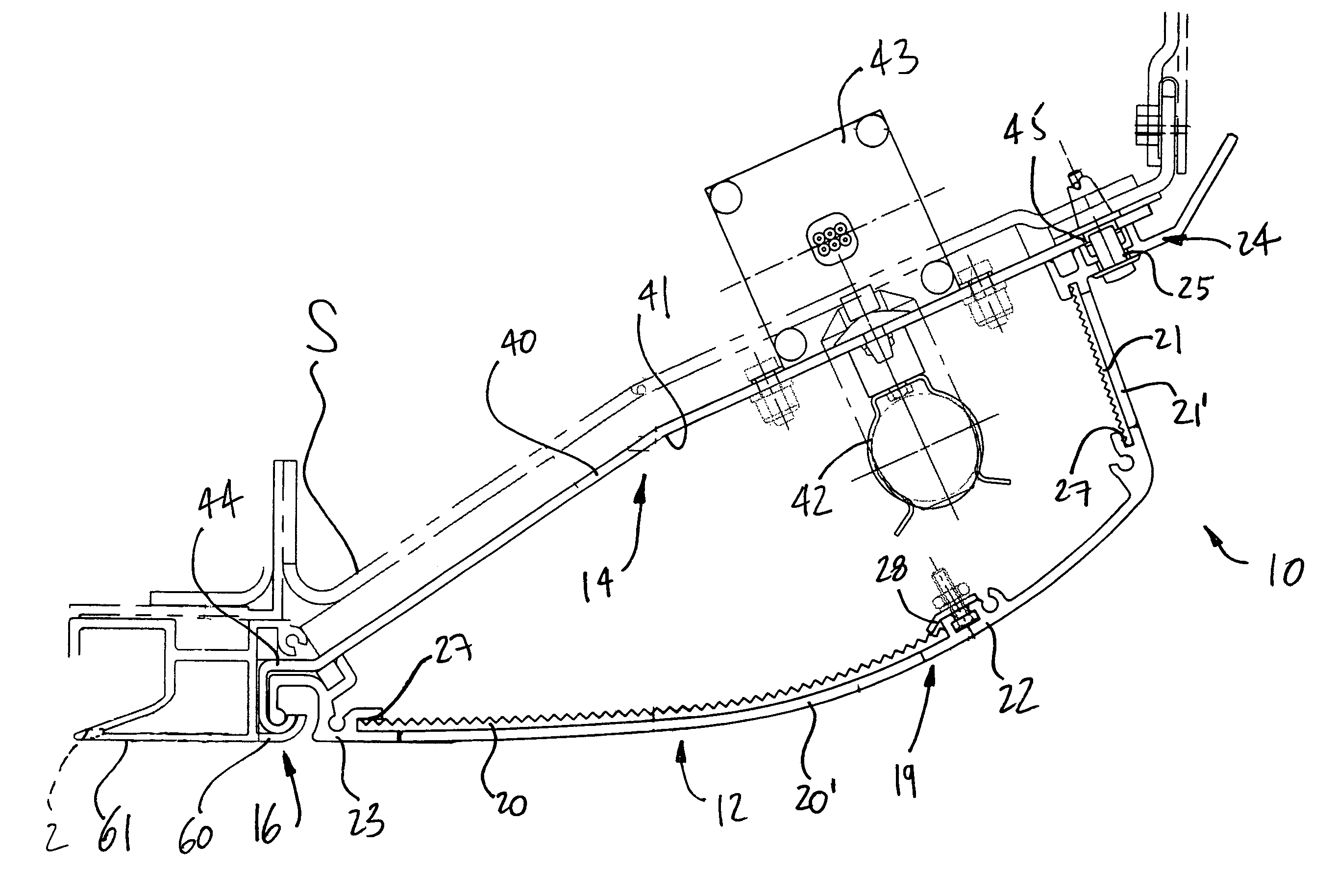
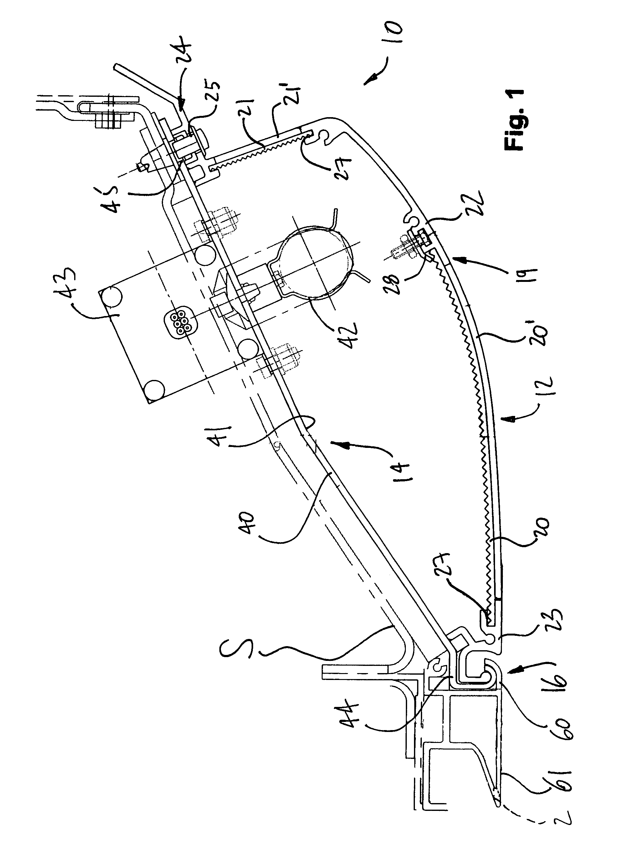
[0022]Referring to the drawings and, more particularly, to FIG. 1, a luminaire assembly in accordance with a preferred embodiment of the present invention is generally shown at 10. The luminaire assembly 10 is mounted to a structure S of a vehicle. The luminaire assembly 10 has a lens member 12, a reflector member 14, and a hinge member 16.

[0023]The lens member 12 is the visible outer shell of the luminaire assembly 10. The lens member 12 diffuses, refracts and / or allows light from a light source to pass therethrough. The lens member 12 conceals the components of the luminaire assembly 10.

[0024]The reflector member 14 is used to reflect light out of the luminaire assembly. The reflector member 14 is a support member that supports various components of the luminaire assembly 10.

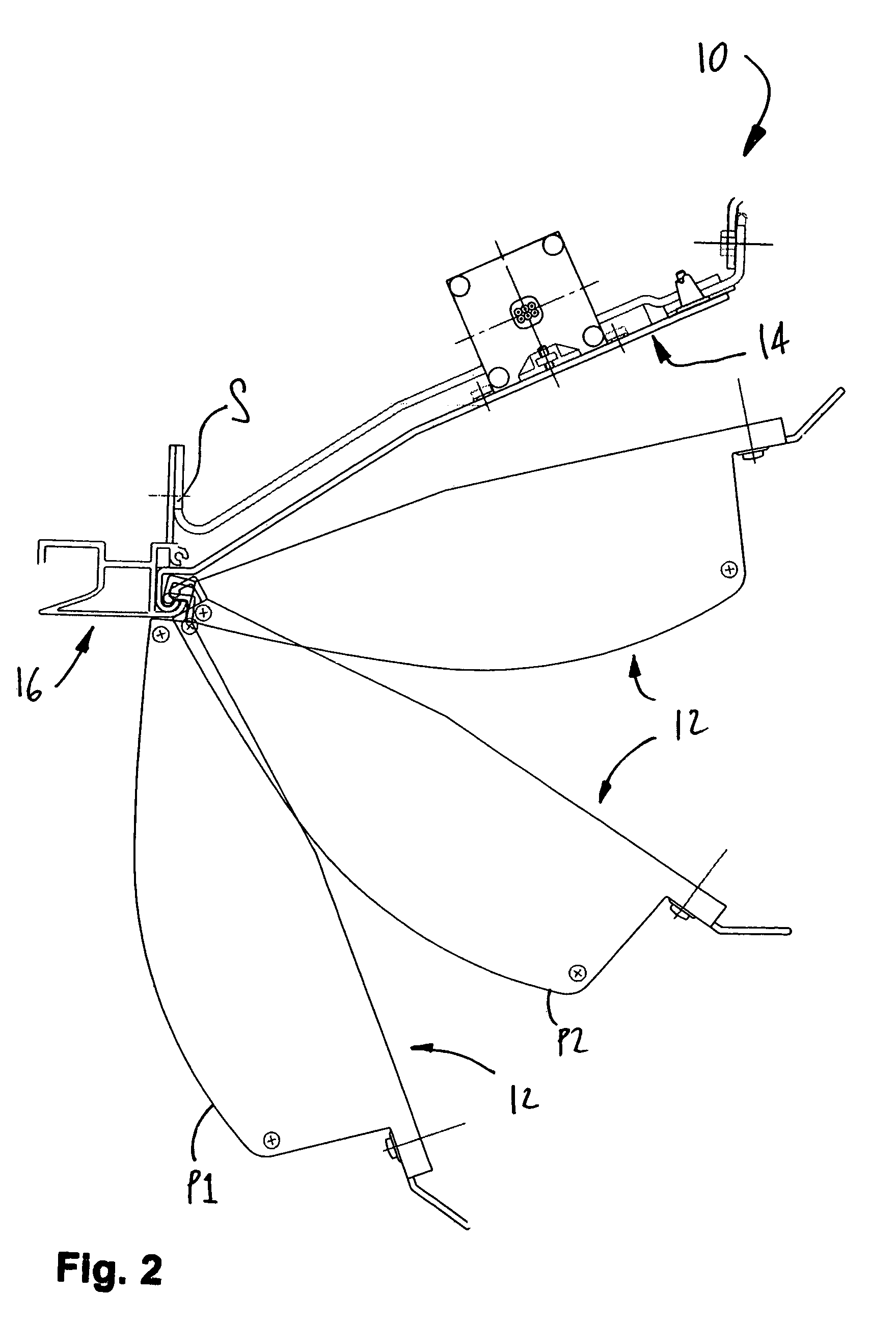
[0025]The hinge member 16 supports the lens member 12 and the reflector member 14 to the structure S of the vehicle such that the lens member 12 and the reflector member 14 are pivotable to an opened, or maint...


PUM


Abstract

A luminaire assembly including a hinge member connected to a structure, a support member, a light source, and an outer shell. The support member is secured to the hinge member to be pivotable between a lighting position, in which electrical components are concealed, and a maintenance position, in which the electrical components are exposed. The light source is supported on a front side of the support member and is operational in the lighting position. The outer shell is secured to the hinge member such as to be pivotable between a closed position, in which the outer shell conceals the light source while being able to allow light from the light source to pass therethrough, and an opened position, in which the outer shell allows access to the light source. A hinge member and method for accessing the electrical components are also presented.

Description

CROSS-REFERENCE TO RELATED APPLICATION[0001]The present patent application claims priority on U.S. Provisional Patent Application No. 60 / 607,255, filed on Sep. 7, 2004, by the present applicant.TECHNICAL FIELD[0002]The present invention generally relates to a luminaire assembly and, more particularly to a luminaire assembly used in public transport vehicles and public areas.BACKGROUND ART[0003]Luminaire assemblies using a fluorescent light source are often used in public transport vehicles, as they are typically energy efficient, with the fluorescent light source being durable with respect to other types of light sources. Such luminaire assemblies may be provided with reflective, refractive and / or diffractive components, the configuration of such components being an important design factor since it plays a key role in determining the light output. Moreover, as public transport vehicles and public areas are typically restricted in space, the sizing of luminaire assemblies installed t...

Claims


Application Information

Patent Timeline
Patent Type & Authority Patents(United States)
IPC IPC(8): F21V17/10E05D1/06F24F13/20
CPCB60Q3/025F21V7/0016F21V17/107Y10T16/535F21Y2103/00Y10T16/542Y10T16/546F21W2101/08B60Q3/43F21W2106/00
Inventor SIBOUT, MICHEL
Owner C E I T CORP
Learn More