
Oscillating brushhead attachment system for a personal care appliance

a technology for personal care appliances and attachment systems, which is applied in the direction of vehicle cleaning, photosensitive materials, instruments, etc., can solve the problems of difficult to maintain the relationship between the two parts to produce the different actions, and the reliability and convenience of attachment becomes more problemati

Active Publication Date: 2008-06-17
LOREAL SA
View PDF12 Cites 115 Cited by
  • Summary
  • Abstract
  • Description
  • Claims
  • Application Information

AI Technical Summary

Benefits of technology

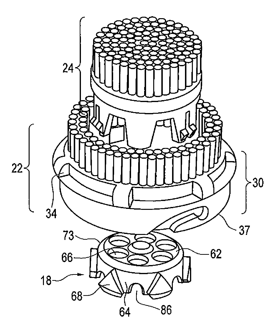
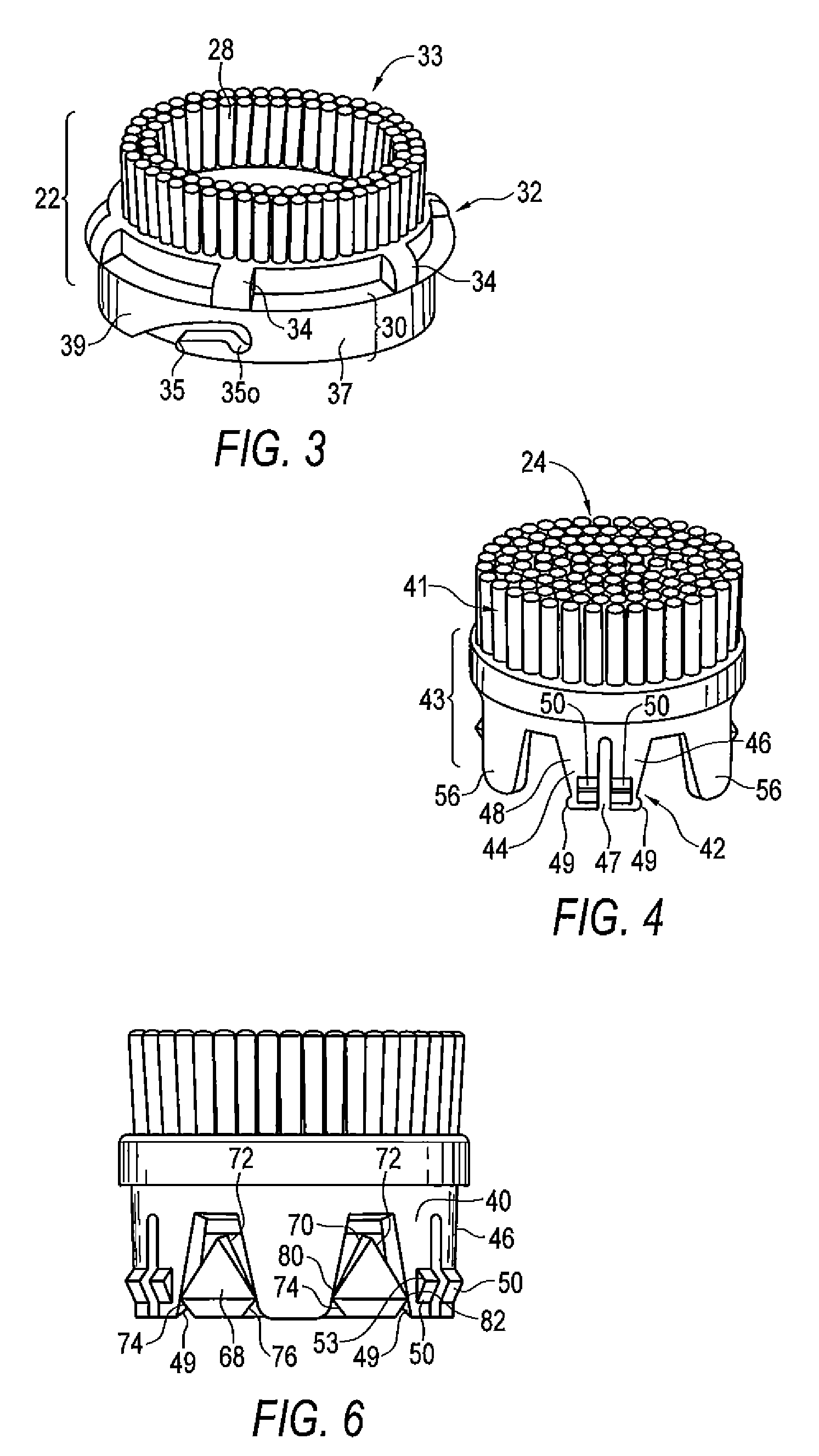
The present invention is a system for attaching a brushhead to a personal care appliance. It includes a hub that is attached to the appliance, an outer brushhead that can be joined to the hub, and an inner brushhead that fits within the outer brushhead. The inner brushhead has legs that fit with the locking elements on the hub, so when the hub moves, the inner brushhead moves as well. The inner brushhead is designed to attach to the outer brushhead, which in turn attaches to the appliance. This system allows for easy attachment of the brushhead to the appliance and ensures that both the outer and inner brushheads are securely connected.

Problems solved by technology

However, with complicated brushhead designs, reliable and convenient attachment becomes more problematic.
For instance, in a brushhead having two or more parts, with each operating differently, such as different motions, there is difficulty in maintaining the two parts in the required relationship to produce the different actions, while also permitting installation of the complete brushhead into the appliance body with a convenient, single easy action.

Method used


Image

  • Oscillating brushhead attachment system for a personal care appliance
  • Oscillating brushhead attachment system for a personal care appliance
  • Oscillating brushhead attachment system for a personal care appliance

Examples


Embodiment Construction

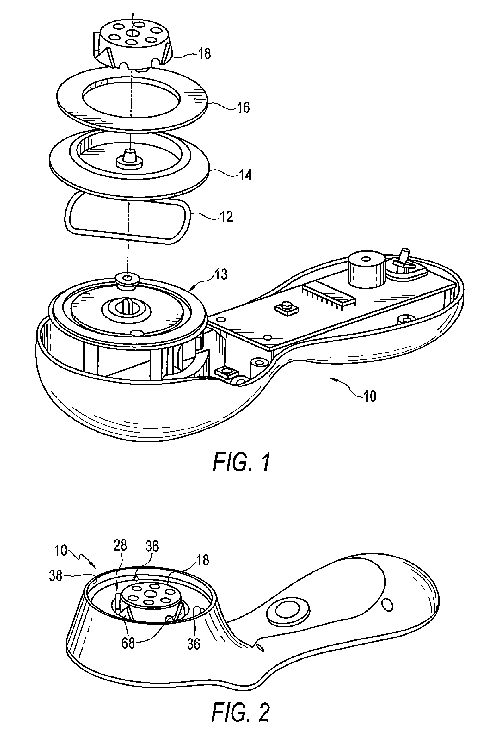
[0012]FIGS. 1 and 2 show a personal care appliance 10 which is described in more detail in co-pending application titled “Motor Providing Oscillating Action for a Personal Care Appliance” and “Brush Configuration for a Powered Skin Cleansing Brush Appliance”, both owned by the assignee of the present invention, the contents of which are hereby incorporated by reference. As shown, personal care appliance 10 is for skin cleaning applications, particularly facial skin. However, appliance 10, as well as the brushhead attachment mechanism shown and described herein, can be used in a variety of other applications, including other skin care applications, such as acne and blackhead treatment; athlete's foot treatment; calloused skin and psoriasis treatment; treatment of razor bumps and related skin applications, such as wound cleansing and treatment of slow or non-healing wounds; scalp cleansing and chemical peel procedures, and shaving cream applicators.

[0013]The personal care appliance 10...


PUM


Abstract

The brushhead attachment system includes a hub member which is secured to a drive shaft of a personal care appliance for oscillating action. The hub member includes a number of spaced locking elements in the form of protrusions around the periphery thereof. An annular outer brushhead portion with a first group of bristles includes a plurality of spaced grooves in the outer surface thereof which mate with extending pins in the body of the appliance for insertion and removal of the outer brushhead portion. An inner brushhead portion is configured to fit within the annular opening of the outer brushhead portion and includes a plurality of depending legs which mate with the protrusions on the drive member for resulting oscillating action of the inner brushhead portion when the drive member oscillates, at least some of the legs having latch elements which fit onto an interior lip of the outer brushhead portion in such a manner that the inner and outer brushhead portions may be installed and removed as a unit, while permitting the inner brushhead portion to be freely rotatable relative to the outer brushhead portion.

Description

TECHNICAL FIELD[0001]This invention relates generally to large brushhead structures for a personal care appliance, such as a skin cleaning apparatus, and more specifically relates to an attachment system for such a brushhead to a driving member in the appliance.BACKGROUND OF THE INVENTION[0002]In personal care appliances, including those having a relatively large brushhead assembly, such as those used for cleaning skin, the brushhead must be readily removable and installable by a user, because of regular replacement requirements, and when installed, must have a solid, positive connection with a drive member for the appliance, such as a rotating shaft, with no or little loss of motion between the drive member and the brushhead. With conventional brushheads, these objectives are accomplished with a variety of attaching structures, including screw-on connections, or snap connections which have tabs to mate with matching openings in the body of the appliance.[0003]However, with complica...

Claims


Application Information

Patent Timeline
Patent Type & Authority Patents(United States)
IPC IPC(8): A46B13/02A46B13/06
CPCA46B13/06A46B2200/1006
Inventor ROTH, DANE M.MEGINNISS, III, STEPHEN M.PILCHER, KENNETH A.REISHUS, RICHARD A.GIULIANI, DAVID
Owner LOREAL SA
Learn More